




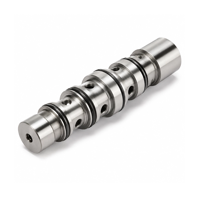

Precision CNC Turned Valve Spools
Precision CNC turned valve spools feature defined diameters, sealing surfaces, and flow-control sections along their length. These details influence the positions at which passages are covered or exposed as the spool moves. Manufactured for hydraulic, pneumatic, and industrial valve assemblies, the components place particular emphasis on the relationship between axial features and the mating surfaces inside the valve mechanism.
Quick Info:
- Material: Stainless Steel / Alloy Steel
- Machining Type: Precision CNC Turning
- Tolerance: ±0.01–0.02 mm
- Surface Finish: Ra 0.4–1.6 μm
- Production Volume: Prototype / Low Volume / Batch Production
- Lead Time: 5–12 Working Days

Get Free Quote


Detailed Description
Inside a hydraulic or pneumatic body, a spool moves between defined positions while its lands open and close fluid routes. Precision valve spools depend on the relative size and spacing of the lands, rather than a single nominal outside diameter. Turned shoulders and relief grooves establish axial geometry for the sliding assembly.
Surface Preparation for Sliding Valve Parts
- As-Machined: Standard finish for general mechanical and valve components.
- Fine Turning: Provides smoother functional surfaces for controlled sliding interfaces.
- Grinding: Available for critical diameters requiring tighter dimensional control.
- Polishing: Reduces surface roughness on sealing and sliding areas.
- Passivation: Improves corrosion resistance for stainless steel components.
- Black Oxide: Available for selected alloy steel components.
Fine turning may satisfy general functional surfaces, while grinding and polishing can address contact areas that need a tighter finish. The finish plan should reference the matching valve bore, fluid cleanliness and intended movement, not appearance alone.
Sealing Lands, Reliefs and Axial Positioning
- Precision Sealing Lands: Controlled diameters support consistent valve sealing and movement.
- Relief Grooves: Reduce interference and help manage fluid distribution.
- Sliding Surfaces: Smooth cylindrical areas support repeated linear motion.
- Shoulder Features: Provide accurate axial positioning inside valve assemblies.
- Flow-Control Profiles: Custom grooves and diameter transitions regulate fluid paths.
A groove may provide a fluid route or relieve interference between neighboring surfaces. Small changes to land width and transition position can affect the valve sequence. Inspection should compare critical features with their common axial datum.
Turning and Finishing of Functional Diameters
- Tight Diameter Control: Critical spool diameters can be maintained for precise sliding and sealing fits.
- Multiple Functional Lands: Several sealing and guiding surfaces can be machined along one component.
- Precision Groove Machining: Relief, oil and retaining grooves can be integrated into the turned geometry.
- Fine Surface Capability: Functional areas can be finished for low-friction movement and improved sealing.
- Custom Valve Geometry: Diameters, shoulders and flow profiles can be produced directly from customer drawings.
- Flexible Production Volumes: Suitable for prototypes, replacement parts and repeat low-volume production.
For precision valve spools, a drawing should define the mating bore, land diameters, overlap positions and required finish. The component can be evaluated for smooth travel and sealing after assembly; a surface specification by itself cannot guarantee a particular leakage rate.
Fluid-Control Assemblies and Spool Uses
- Hydraulic Valves
- Pneumatic Valves
- Directional Control Systems
- Pressure Control Equipment
- Industrial Automation
- Actuator Systems
- Fluid Control Equipment
- Production Machinery
Directional-control and pressure-control assemblies call for different land arrangements. A replacement spool also needs confirmation of the original valve-body geometry, because similar outer profiles may conceal different flow timing.

Frequently Asked Questions
-
Why do land diameters matter?

-
They form the sliding and sealing interfaces against the valve bore.
-
Can more than one land be machined on the same spool?
-
Yes. CNC turning can form multiple stepped diameters, lands and shoulders along one axis.
-
When would grinding be considered?
-
Grinding may suit selected critical diameters or finishes after turning, subject to the material and tolerance requirements.
-
Do relief grooves control fluid flow?
-
Grooves can provide clearance or connect flow paths as specified.
-
Which materials are available?
-
Stainless steel and selected alloy steels can address different corrosion, strength and wear conditions.
-
Can a spool be copied from an existing sample?
-
A sample can support an initial review, but mating dimensions and functional requirements are needed before confirming compatibility.
-
What needs checking during inspection?
-
Land diameters, spacing, runout-sensitive surfaces, groove positions and finish requirements are typical inspection points.
-
Does a smooth surface guarantee zero leakage?
-
No. Leakage depends on clearance, pressure, fluid properties, wear and the full valve assembly.
-
Can prototype spools be followed by small batches?
-
Yes. Approved drawings and the agreed inspection plan can support successive machining batches.


