




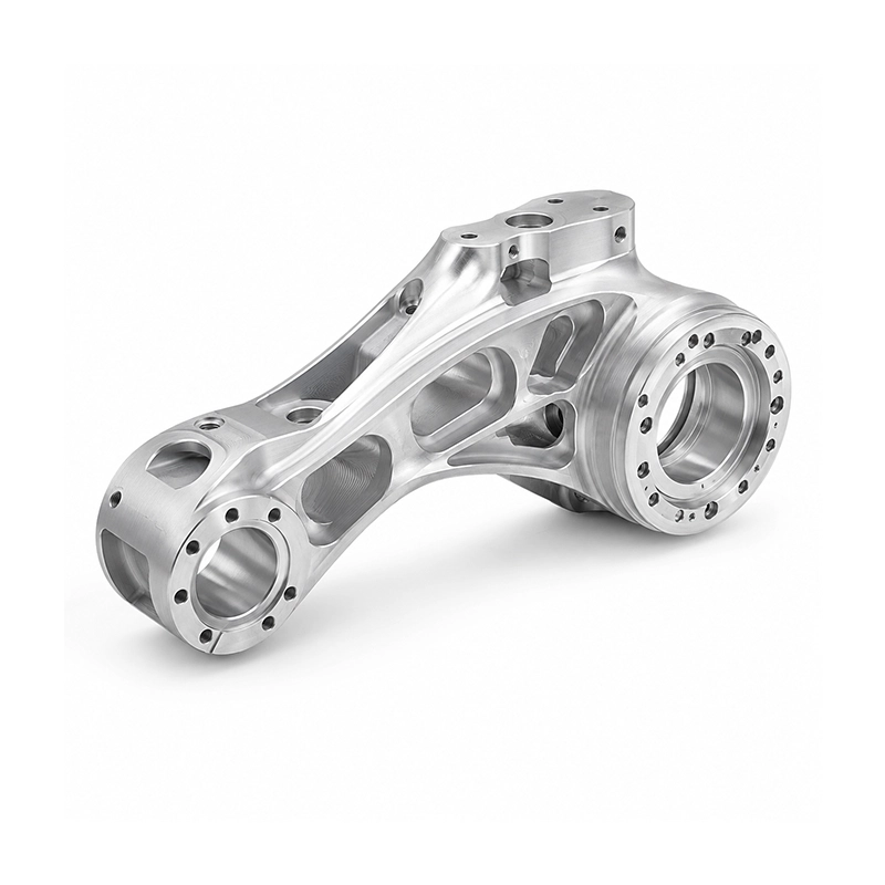

5-Axis CNC Robotic Arm Components
Custom five-axis CNC machined robotic arm parts can feature joint interfaces, weight-saving pockets, and mounting points arranged across several faces. Multi-axis access supports the machining of geometry around compact connection areas, including surfaces that are difficult to reach with simpler setups. These components are suited to robotic mechanisms and automated motion equipment where structural shape, clearance, and attachment positions have to work together within the assembly.
Quick Info:
- Material: Aluminum 6061 / 7075, Stainless Steel
- Machining Type: 5-Axis CNC Machining
- Tolerance: ±0.02–0.05 mm
- Surface Finish: Ra 0.8–3.2 μm
- Production Volume: Prototype / Low Volume / Batch Production
- Lead Time: 5–15 Working Days

Get Free Quote


Detailed Description
An articulated arm depends on the relationship between its bearing center, actuator mount and neighboring links. CNC machined robotic arm parts can include joint housings, motor connection faces and lightened structural arms machined from a common solid blank. Pockets between attachment zones reduce material where the design permits, while the main joint interfaces remain available for accurate seating.
Five-axis machining reaches angled fastening locations and features around a three-dimensional arm profile. Aluminum 6061 supports many general structures; 7075 may be considered for higher-strength needs. Stainless steel is an option for selected contact or wear-related regions.
Available Surface Finishes
- As-Machined: Suitable for internal robotic and automation components.
- Bead Blasting: Produces a uniform matte surface.
- Clear Anodizing: Improves corrosion resistance for aluminum robotic components.
- Black Anodizing: Common for industrial robotics and automation systems.
- Hard Anodizing: Adds wear resistance around frequently assembled interfaces.
- Passivation: Suitable for stainless steel robotic components.
Bead blasting and anodizing provide different surface outcomes for aluminum components. Finish callouts should distinguish cosmetic regions from bearing seats, threaded holes and electrical contact areas that may need different treatment.
Structural & Functional Breakdown
- Precision Joint Interfaces: Support accurate alignment between rotating robotic assemblies.
- Bearing & Shaft Seats: Provide controlled locations for motion-system components.
- Weight-Reduction Pockets: Reduce moving mass without removing material from critical load paths.
- Actuator Mounting Features: Integrate motor and gearbox interfaces into the structure.
- Multi-Angle Mounting Faces: Support sensors, cables and auxiliary components at different orientations.
Bearing bores and shaft seats establish rotational references. The geometry around them also needs room for gearbox hardware, cable routing and the next joint in the assembly. Removing mass near an interface requires a review of the load path rather than a purely visual pocket layout.
Key Features
- Lightweight Structural Design: Material can be removed from low-load regions to reduce robotic arm inertia.
- Precision Joint Geometry: Bearing bores, shaft interfaces and mounting faces can be accurately related.
- Complex Multi-Side Features: 5-axis machining reaches functional geometry distributed across several orientations.
- Integrated Mounting Interfaces: Motors, gearboxes, sensors and end effectors can connect directly to machined features.
- High-Strength Material Options: Aluminum 7075 and stainless steel support more demanding structural requirements.
- Flexible Production Volumes: Suitable for robotic prototypes, engineering validation and low-volume equipment production.
On a collaborative robot elbow, CNC machined robotic arm parts can combine an actuator face, a bearing seat and nearby lightening cavities. Trial assembly checks whether the fasteners remain accessible and whether adjacent parts have sufficient clearance through the expected range of movement.
Applications
- Industrial Robots
- Collaborative Robots
- Robotic Arms
- End-Effector Systems
- Automated Assembly Equipment
- Motion Control Systems
- Inspection Robots
- Custom Automation Equipment
Document the joint datums, bearing fit, material choice and any critical surface controls. Motional performance, fatigue and load capacity depend on the full robotic system and require their own engineering validation.

Frequently Asked Questions
-
Why are bearing seats important in a robot link?

-
They locate rotating elements relative to the structural arm and adjoining joints. Required fit and orientation depend on the mechanism.
-
Can weight-reduction pockets be added near joints?
-
Pockets can be placed in selected regions, but material removal must respect the expected load path and any stiffness requirements.
-
Which aluminum grades are mentioned for these components?
-
6061 and 7075 are included as options for different strength and weight requirements.
-
How does five-axis machining help with an arm link?
-
It provides tool access to angled faces, bearing interfaces and mounting patterns distributed around the link.
-
Can motor and gearbox interfaces be machined together?
-
Both may be included in the same component when the design and workholding allow it.
-
Will anodizing change a precision bearing fit?
-
Surface treatment can change dimensions. Bearing seats or other tight interfaces may need masking or process-specific allowances.
-
Can cable-routing features be incorporated?
-
Clearance slots and other paths can be considered where they do not compromise the intended structure.
-
What information supports a robotic arm component review?
-
Provide the full CAD assembly, mating interfaces, bearing and actuator details, material, intended loads and critical dimensions.


