




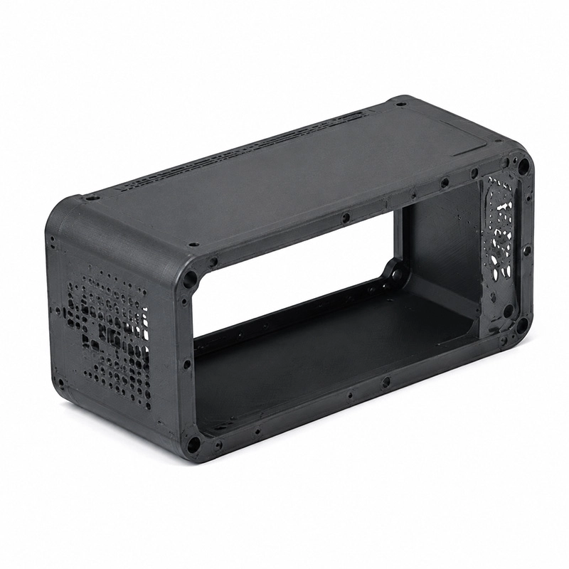

3D Printed Product Prototype Housings
Custom 3D printed prototype housings provide physical samples for checking internal space, component placement, external contours, and connection features. Used in electronics, consumer products, and industrial equipment, these prototypes allow engineers to examine how individual parts fit within an enclosure and assess its overall form. The ability to produce complex shapes without dedicated molds also makes it practical to explore design changes during early product development.
Quick Info:
- Process: SLA / SLS / MJF 3D Printing
- Material: Resin / Nylon / ABS-like Resin
- Tolerance: ±0.05–0.15 mm
- Wall Thickness: 1.0–5.0 mm
- Lead Time: 3–7 Working Days

Get Free Quote


Detailed Description
3D printed prototype housings give product shells a physical form before injection mold tooling begins. Electronic control covers, handheld instrument cases and equipment panels can include screw bosses, openings for ports, ventilation slots and snap-fit edges directly in a CAD-based print. The resulting shell helps reveal whether components sit correctly inside the enclosure and whether the two halves close as intended.
For appearance reviews, SLA can reproduce fine contours and provide a surface suited to additional sanding or painting. When a housing needs repeated handling or mechanical fit checks, nylon-based SLS or MJF may offer a more appropriate material option. Selection still depends on wall thickness, feature geometry and the kind of loading expected during each trial.
Available Surface Finishes
- Sanding: Removes layer marks and improves appearance.
- Painting: Creates production-like color finishes.
- Polishing: Provides smooth cosmetic surfaces.
- Texture Treatment: Simulates injection molded textures.
- Coating: Adds additional surface protection.
A connector opening that looks correct on screen may interfere with a real cable boot. Similarly, an internal standoff can be moved after the first assembly exposes board-height or screw-access problems. Revision files make these changes without committing to hardened steel tooling.
Structural & Functional Breakdown
- Snap-Fit Features: Supports assembly testing without fasteners.
- Internal Mounting Bosses: Validates component installation.
- Ventilation Structures: Tests thermal design concepts.
- Thin Wall Sections: Evaluates product weight and appearance.
- Complex External Surfaces: Supports industrial design verification.
Surface treatments can help check the intended product appearance, but paint thickness and texture may change the clearance around snap features or threaded inserts. Functional interface areas should remain available for direct inspection.
Key Features
- Fast Housing Development: Produces complete product shells directly from CAD files.
- Appearance Validation: Supports realistic evaluation of product design.
- Assembly Testing: Verifies component fit and mechanical interfaces.
- Multiple Material Simulation: Resin and nylon options support different requirements.
- Custom Surface Finishing: Creates near-production appearance.
- Prototype Design Iteration: Helps identify redesign issues before tooling.
On a compact controller housing, a recessed button, ventilation pattern and circuit-board supports can occupy the same shell while still leaving room for wiring. 3D printed prototype housings make it possible to review those relationships through physical assembly and handling.
Applications
- Consumer Electronics
- Smart Devices
- Industrial Equipment
- Control Systems
- Household Products
- IoT Devices
- Electronic Enclosures
A finished appearance model is not a substitute for qualification of the eventual molded polymer. Molded-part shrinkage, gate placement, draft and long-term snap retention still need separate engineering review.

Frequently Asked Questions
-
Which printing process is suitable for checking an enclosure finish?

-
SLA can reproduce smooth external contours for appearance models. Sanding, primer and painting may further change the visual result; the finish specification should match the purpose of the review.
-
Can a housing prototype include functional snap fits?
-
Snap-fit fingers and mating slots can be printed for initial assembly checks. Their behavior depends on material, thickness, build orientation and how often the joint opens and closes.
-
How can circuit-board mounting points be tested?
-
Print internal bosses and support posts in the planned locations, then fit the actual PCB, screws and connectors. Check screw access, board height and clearance to the lid.
-
Are SLS and MJF suitable for repeated handling tests?
-
Nylon-based SLS and MJF prints can support handling and fit evaluations. Their behavior will differ from a final injection-molded material and must be assessed for the specific geometry.
-
Can transparent windows and opaque shells be evaluated together?
-
Separate prototype pieces can represent viewing windows and opaque housing sections. The fit between them can be checked, although final optical clarity requires the intended production material and finish.
-
Will a printed snap-fit indicate the exact performance of a molded snap-fit?
-
No. It can reveal assembly direction and obvious interference, but the printed material, layer structure and molded part properties differ.
-
Which dimensions need special attention on the drawing?
-
Mark connector openings, board locators, parting interfaces, mounting holes and any critical clearances. These are the areas that most directly affect assembly.
-
Can housing geometry change between prototype batches?
-
Yes. CAD updates can alter wall thickness, vent spacing, fastening locations or external contours without changing a production mold.
-
What should accompany a CAD file for a housing review?
-
Include assembled component dimensions, material preferences, expected handling, finish requirements and any critical tolerance notes.


