
Die – Casting Process: Innovation and Excellence Led by TOP Prototype

1. Introduction to Die – Casting Process
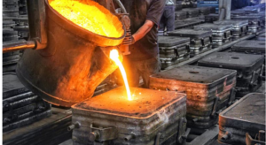
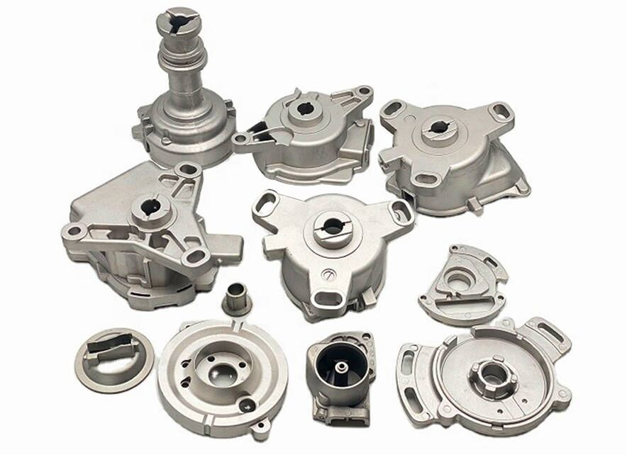
Die – casting is a highly efficient manufacturing technology that has been widely adopted across multiple industrial sectors, ranging from automotive and aerospace to electronics and medical equipment. Its primary function is to produce complex metal components characterized by high precision and consistent quality, which are essential for the reliable operation of end – products in these industries. The core mechanism of this process involves applying high pressure to force molten metal into a pre – fabricated mold cavity—this cavity is engineered to replicate the exact shape and details of the target component. Once inside the cavity, the molten metal undergoes a controlled cooling and solidification process. During this stage, heat is transferred from the molten metal to the mold, causing the metal to transition from a liquid to a solid state, eventually taking on the shape predefined by the mold with minimal deviations.
This manufacturing method has achieved widespread recognition due to its unique capabilities that address key challenges in modern production. Specifically, it enables the mass production of parts with tight dimensional tolerances—often within a range of ±0.005 to ±0.01 inches—smooth surface finishes (typically ranging from Ra 1.6 to Ra 6.3 μm), and complex geometric structures such as internal cavities, thin walls (as thin as 0.5 mm for some alloys), and intricate external features. These features are often challenging to realize through alternative manufacturing approaches like sand casting or forging, which may require additional post – processing steps or struggle to maintain consistency in high – volume production. The die – casting process can be broken down into several sequential stages, each of which exerts a critical influence on the final quality of the manufactured part. Any deviation in one stage can propagate through the entire process, leading to defects such as porosity, shrinkage, or dimensional inaccuracies.
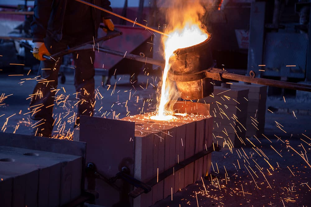
First, the mold—commonly referred to as the die—is designed and fabricated in strict accordance with the specific requirements of the target part, which are typically outlined in detailed engineering drawings or 3D models. To withstand the extreme conditions of high pressure (often 10 to 150 MPa) and temperature (ranging from 450°C for zinc alloys to 700°C for aluminum alloys) during the process, the die is typically constructed using high – strength steel materials such as H13 or P20 tool steel. These steels undergo heat treatment processes like quenching and tempering to enhance their hardness, wear resistance, and thermal fatigue resistance, ensuring a long service life of the die—often thousands to hundreds of thousands of cycles. Second, the preparation of molten metal takes place in dedicated melting furnaces. Non – ferrous metals, such as aluminum, zinc, and magnesium alloys, are the most commonly used materials in die – casting due to their low melting points, good fluidity, and favorable mechanical properties. For example, aluminum alloy A380 is widely used in automotive components for its high strength and corrosion resistance, while zinc alloy ZAMAK 3 is preferred for small – to – medium – sized parts like hardware fittings due to its excellent castability. These metals are melted in a specialized furnace at a precisely controlled temperature—for instance, aluminum alloys are typically melted at 650°C to 700°C—to form the molten state required for the process. During melting, flux or inert gas may be used to remove impurities and prevent oxidation, ensuring the purity of the molten metal.
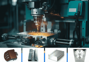
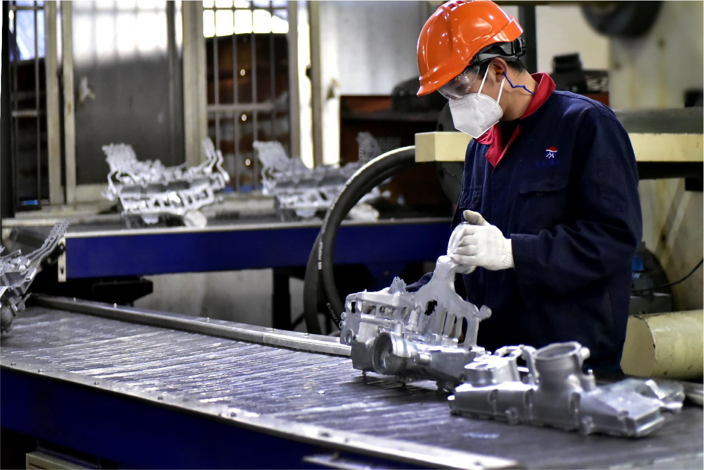
Subsequently, the molten metal is injected into the die cavity under high pressure using a hydraulic or mechanical injection system. The pressure applied in this stage can range from several thousand to hundreds of thousands of pounds per square inch (psi), with the exact value depending on the type of metal, the complexity of the part, and the size of the die cavity. This high pressure is maintained until the metal has fully solidified, a stage known as the “hold time.” The hold time is critical as it ensures that the metal completely fills the mold cavity, compensates for any shrinkage that occurs during solidification, and retains the desired shape without deformation. The injection speed is also a key parameter—typically ranging from 0.5 m/s to 5 m/s—which needs to be optimized to prevent turbulence in the molten metal (which can trap gas and cause porosity) while ensuring rapid filling of the cavity. Finally, the die is opened using a die – opening mechanism, and the solidified component—known as the casting—is removed either manually or by automated robotic arms. Any excess material, such as flash (thin layers of metal that form between the two halves of the die) or runner systems (channels that deliver molten metal to the cavity), is trimmed off using specialized cutting tools like band saws or CNC routers. In some cases, the casting may also undergo additional finishing procedures, including machining (to achieve tight dimensional tolerances), polishing (to improve surface finish), or coating (such as anodizing for aluminum parts to enhance corrosion resistance) to meet the required surface quality and dimensional accuracy standards of the end – application.
2. TOP Prototype: A Leader in Die – Casting Technology
In the competitive field of die – casting, TOP Prototype has established itself as a prominent provider of high – quality die – casting solutions, catering to the diverse needs of clients across global industries. With over a decade of accumulated experience in the manufacturing industry, the company has developed an in – depth understanding of the die – casting process—from die design and material selection to process optimization and quality control. This expertise allows TOP Prototype to address even the most complex challenges faced by clients, such as producing parts with ultra – thin walls or tight tolerance requirements. Moreover, TOP Prototype has made significant investments in advanced technology and equipment, allocating a substantial portion of its annual budget to research and development (R&D) and equipment upgrades. This commitment to innovation enables it to deliver exceptional results to its clientele, consistently meeting or exceeding industry standards.
2.1 Advanced Technology and Equipment
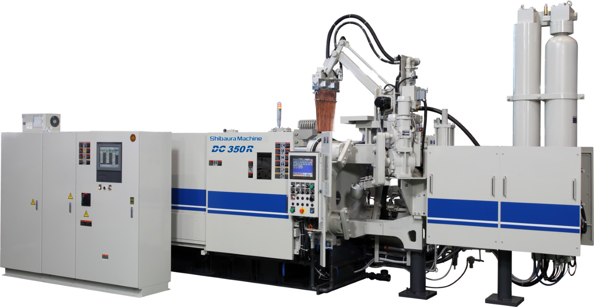
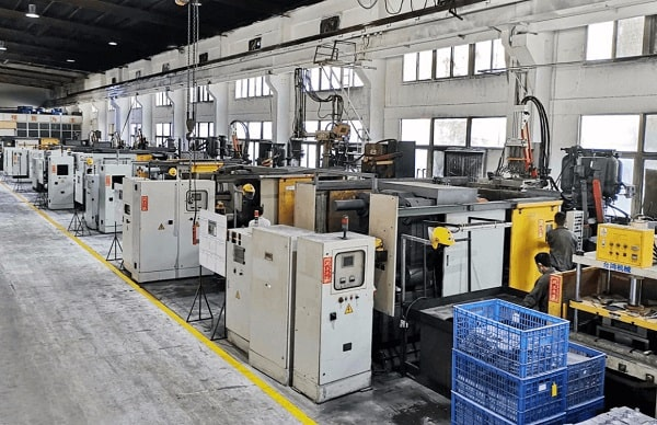
TOP Prototype is equipped with a fleet of state – of – the – art die – casting machines, sourced from leading global manufacturers such as Buhler and Idra. These machines cover a wide range of clamping forces—from 50 tons to 1200 tons—allowing the company to handle a wide variety of metal alloys and produce parts of varying sizes and levels of complexity. For example, the 50 – ton machines are used for small, precision parts like electronic connectors, while the 1200 – ton machines are employed for large automotive components such as engine blocks or transmission housings. A key feature of these machines is their advanced control systems, which are based on programmable logic controllers (PLCs) and human – machine interfaces (HMIs). These systems allow for real – time monitoring and precise adjustments to critical process parameters, including pressure, temperature, injection speed, and hold time. Operators can set up multiple process profiles for different parts, ensuring that each part manufactured meets the highest quality standards. Additionally, some of the machines are equipped with closed – loop control systems, which use sensors to detect deviations in process parameters and automatically adjust them, further enhancing the consistency and reliability of the production process.
In addition to advanced machinery, TOP Prototype leverages cutting – edge computer – aided design (CAD) and computer – aided manufacturing (CAM) software, including industry – leading tools like SolidWorks, AutoCAD, and Mastercam. These software tools play a vital role in the design and manufacturing of dies. During the die design phase, CAD software is used to create 3D models of the die, allowing engineers to simulate the flow of molten metal using computational fluid dynamics (CFD) software. This simulation helps identify potential issues such as air entrapment or uneven filling, which can be addressed before the die is manufactured, reducing the risk of costly rework. CAM software, on the other hand, is used to generate toolpaths for CNC machining centers, which are used to fabricate the die components with high precision. This enables the creation of complex and precise die geometries—such as conformal cooling channels, which improve the uniformity of cooling during the casting process—that would be difficult to achieve through traditional manual machining methods. Furthermore, the use of CAD/CAM software significantly accelerates the die design and manufacturing process. What would take weeks using traditional methods can now be completed in days, thereby reducing the lead time for die – casting projects and allowing clients to bring their products to market faster.
2.2 Quality Control Measures
Quality is a top priority at TOP Prototype, and the company adheres to strict international quality standards such as ISO 9001:2015 and IATF 16949 (for automotive components). To ensure the highest level of quality, the company has implemented a comprehensive quality control (QC) system that follows the Plan – Do – Check – Act (PDCA) cycle. This system covers every stage of the die – casting process, starting from the initial design and manufacturing of the die and extending to the final inspection of the casting, as well as post – delivery support.
Before a die is put into production, it undergoes a rigorous inspection process conducted by a team of qualified QC engineers. This inspection includes dimensional measurement using coordinate measuring machines (CMMs) to verify that the die meets all design specifications, as well as visual inspection to check for surface defects such as cracks, scratches, or uneven surfaces. In some cases, a trial run (known as a “die tryout”) is conducted to produce a small batch of castings. These trial castings are inspected to evaluate the performance of the die, including the filling of the cavity, the formation of the part features, and the absence of defects. Any issues identified during the die tryout are addressed by modifying the die or adjusting the process parameters before full – scale production begins.
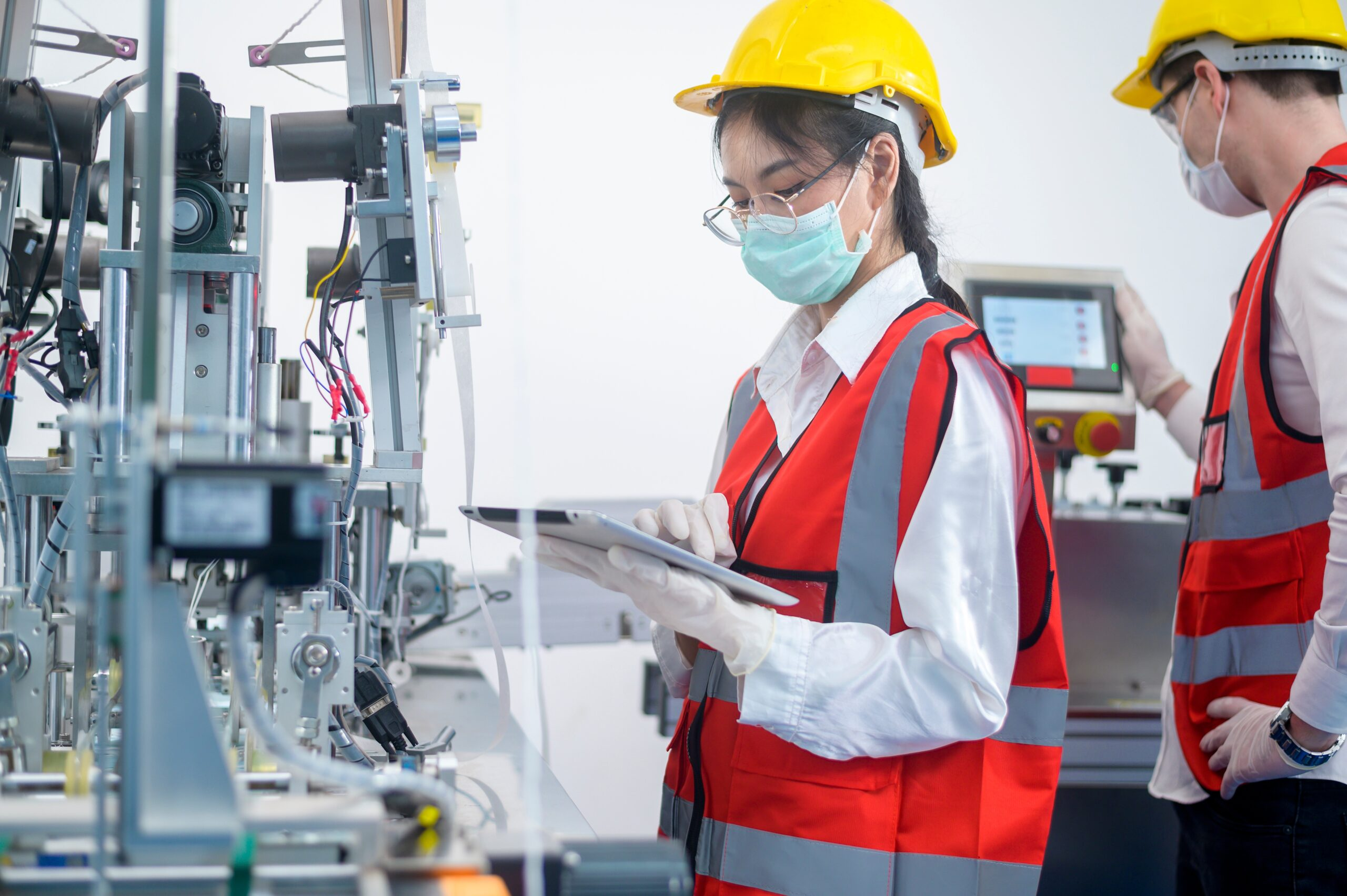
During the die – casting process itself, regular sampling of the castings is conducted at predefined intervals—typically every 30 minutes or after every 100 parts. These samples are inspected in a dedicated QC laboratory to assess dimensional accuracy, surface quality, and mechanical properties. For dimensional accuracy, CMMs with a measurement accuracy of up to ±0.001 mm are used to measure key dimensions of the part, comparing them to the design specifications. Surface quality is evaluated using visual inspection and surface roughness testers, which measure the Ra value of the part surface. Mechanical properties such as tensile strength, yield strength, and elongation are tested using tensile testing machines, which pull the sample until it breaks and record the force and deformation data. If any deviations from the required standards are detected—such as a dimension that is outside the tolerance range or a surface roughness value that exceeds the limit—immediate action is taken to address the issue. This may involve adjusting the process parameters (e.g., increasing the injection pressure or modifying the cooling time), repairing the die, or replacing the molten metal batch. The root cause of the deviation is also investigated using tools like fishbone diagrams or 5 – Whys analysis to prevent similar issues from occurring in the future.
To further enhance the quality verification process, TOP Prototype utilizes a range of advanced testing equipment beyond CMMs and tensile testing machines. For example, the company uses X – ray fluorescence (XRF) spectrometers to analyze the chemical composition of the molten metal, ensuring that it meets the required alloy specifications. This is particularly important for industries like aerospace, where the chemical composition of the material directly affects its mechanical and corrosion resistance properties. Additionally, ultrasonic testing (UT) and magnetic particle inspection (MPI) are used to detect internal and surface defects in the castings that may not be visible to the naked eye. UT uses high – frequency sound waves to penetrate the casting and identify voids or cracks, while MPI uses magnetic fields to detect surface cracks in ferromagnetic materials like some steel dies. These non – destructive testing (NDT) methods allow TOP Prototype to ensure the integrity of the castings without damaging them, making them suitable for critical applications.
2.3 Industry – Specific Application Cases
TOP Prototype’s die – casting solutions have been successfully applied in a wide range of industries, with tailored approaches to meet the unique requirements of each sector. In the automotive industry, the company has partnered with several leading automotive manufacturers to produce key components such as aluminum die – cast engine brackets and zinc die – cast door handles. For the engine brackets, which require high strength and rigidity to support the weight of the engine, TOP Prototype selected aluminum alloy A356 (heat – treated to T6 condition) for its excellent mechanical properties. The die design included conformal cooling channels to ensure uniform cooling of the bracket, reducing the risk of shrinkage defects. During production, the process parameters were optimized to achieve a tensile strength of 310 MPa and a yield strength of 276 MPa, meeting the automotive manufacturer’s strict requirements. The final brackets underwent rigorous testing, including vibration testing and load testing, to ensure they could withstand the harsh operating conditions of a vehicle.
In the electronics industry, TOP Prototype has produced magnesium alloy housings for portable electronic devices such as laptops and tablets. Magnesium alloy AZ91D was chosen for this application due to its low density (1.81 g/cm³), which helps reduce the weight of the device, and its good electromagnetic shielding properties, which protect the internal electronic components from external interference. The housing design featured thin walls (1.2 mm thick) and complex internal ribs to provide structural support while minimizing weight. To achieve these thin walls without defects, TOP Prototype used a high – speed injection system (injection speed of 4 m/s) to ensure rapid filling of the die cavity. The final housings had a surface roughness of Ra 3.2 μm, which was achieved through a combination of precise die polishing and post – casting vibratory finishing. The housings also underwent corrosion resistance testing, where they were exposed to a salt spray environment for 24 hours, with no signs of corrosion observed—meeting the electronics manufacturer’s durability standards.
3. Future Trends in Die – Casting Process
The die – casting industry is in a state of continuous evolution, driven by the increasing demand for high – quality, lightweight, and complex parts across various industrial sectors, as well as the growing emphasis on sustainability and digitalization. One of the key future trends in the die – casting process is the development of new metal alloys that offer enhanced performance and environmental benefits.
With the growing global focus on environmental protection and energy conservation—particularly in the automotive industry, where stricter emissions regulations are being implemented—there is a rising demand for lightweight metal alloys that can reduce the weight of products, thereby improving energy efficiency. Magnesium alloys, which are even lighter than aluminum alloys, are gaining increasing popularity in this context. However, traditional magnesium alloys have limitations such as low corrosion resistance and poor high – temperature performance. To address these issues, researchers and manufacturers are developing new magnesium – based alloys with the addition of elements like rare earth metals (e.g., neodymium or cerium) or calcium. These alloying elements can significantly improve the corrosion resistance and high – temperature strength of magnesium alloys, expanding their application range to critical components like automotive engine parts. TOP Prototype is closely monitoring the development of these new metal alloys and is investing in research and development activities to expand its capabilities in processing these advanced materials. The company has established a dedicated R&D team that collaborates with academic institutions and material suppliers to test and optimize the die – casting process for new alloys. For example, the team has conducted trials on a new magnesium – rare earth alloy, adjusting the melting temperature, injection pressure, and cooling rate to achieve high – quality castings with minimal defects.
Another significant future trend is the integration of smart technology into the die – casting process, which is part of the broader Industry 4.0 revolution. The application of Internet of Things (IoT) devices, artificial intelligence (AI), and big data analytics holds great promise for the industry, enabling more efficient, flexible, and intelligent production. IoT devices—such as temperature sensors, pressure sensors, and vibration sensors—can be installed on die – casting machines, dies, and furnaces to collect real – time data on various process parameters, including pressure, temperature, injection speed, cooling time, and die wear. These sensors transmit data to a centralized cloud platform, where it is stored and processed. AI and big data analytics algorithms are then used to analyze this large volume of data to identify patterns and trends that may not be visible to human operators. For example, the algorithms can detect subtle changes in temperature distribution across the die, which may indicate the onset of die wear or a potential defect in the casting. The insights derived from this analysis can be used to optimize process parameters in real – time—for instance, automatically adjusting the cooling time if the temperature data suggests that the casting is not solidifying properly—predict potential defects before they occur, and reduce equipment downtime by scheduling preventive maintenance based on the data on die wear or machine performance.
TOP Prototype is actively exploring the integration of these smart technologies into its die – casting operations to enhance its competitiveness in the market. The company has already piloted an IoT – based monitoring system on several of its die – casting machines. In this pilot, temperature sensors were embedded in the die to measure the temperature distribution during the casting process, and pressure sensors were installed in the injection system to monitor the injection pressure. The data collected by these sensors was analyzed using a machine learning algorithm that had been trained on historical data of high – quality castings. The algorithm was able to predict the quality of the casting in real – time, with an accuracy of over 90%. If the algorithm predicted a potential defect, it sent an alert to the operator, who could then adjust the process parameters or stop the machine to prevent the production of defective parts. This pilot project resulted in a 15% reduction in defect rates and a 10% increase in production efficiency, demonstrating the potential of smart technology in die – casting.
A third emerging trend in the die – casting industry is the combination of die – casting with additive manufacturing (AM), also known as 3D printing. Additive manufacturing offers unique advantages such as the ability to produce complex geometries with minimal material waste, making it a complementary technology to die – casting. One of the key applications of AM in die – casting is the production of die inserts with complex internal features, such as conformal cooling channels. Conformal cooling channels are designed to follow the shape of the casting, ensuring uniform cooling and reducing the cooling time, which can improve the quality of the casting and increase production efficiency. However, producing conformal cooling channels using traditional machining methods is often difficult or impossible due to their complex shape. Additive manufacturing, particularly metal AM processes like selective laser melting (SLM), can produce these complex die inserts with high precision. TOP Prototype has already adopted this approach, using SLM to produce die inserts with conformal cooling channels for several of its clients. For example, the company produced a die insert for a zinc die – cast automotive component with a complex curved shape. The conformal cooling channel in the insert reduced the cooling time by 30%, resulting in a 20% increase in production throughput and a significant reduction in shrinkage defects in the casting.
4. Conclusion
The die – casting process is a fundamental manufacturing technology that plays a crucial role in the production of high – quality, complex metal parts for a wide range of industries, including automotive, aerospace, electronics, and medical equipment. Its high production efficiency—capable of producing thousands of parts per day—ability to achieve high precision (with tolerances as tight as ±0.005 inches), and capacity to produce complex geometries (such as thin walls and internal cavities) have made it an indispensable part of modern manufacturing. As industries continue to demand more advanced and sustainable products, the die – casting process will remain a key enabler of innovation and progress.
TOP Prototype, through its adoption of advanced technology (including state – of – the – art die – casting machines and CAD/CAM software), implementation of strict quality control measures (covering every stage of the process and utilizing advanced testing equipment), and commitment to meeting customer needs (through tailored solutions and industry – specific expertise), has established itself as a leader in the die – casting industry. The company’s successful application cases in the automotive and electronics industries demonstrate its ability to deliver high – quality, reliable die – casting solutions that meet the most demanding requirements of clients.
As the die – casting industry continues to evolve, driven by trends such as the development of new metal alloys, the integration of smart technology, and the combination with additive manufacturing, TOP Prototype is well – positioned to embrace these changes and overcome emerging challenges. By continuing to invest in new technologies (through R&D and equipment upgrades), develop new capabilities (such as processing advanced alloys and implementing smart manufacturing systems), and maintain its focus on quality and customer satisfaction, the company will continue to lead the way in the die – casting industry. In the future, TOP Prototype aims to further expand its global presence, collaborate with more clients across diverse industries, and contribute to the advancement of the die – casting technology by developing innovative solutions that address the evolving needs of the market. Whether it is for producing lightweight automotive components to reduce emissions, precision electronic housings to protect sensitive devices, or complex aerospace parts to ensure flight safety, TOP Prototype will remain the trusted partner for all die – casting needs.