• Home
  • 未分类
  • Precision Redefined: CNC Machining for Automotive Camshafts by TOP Prototype

Precision Redefined: CNC Machining for Automotive Camshafts by TOP Prototype

Precision Redefined: CNC Machining for Automotive Camshafts by TOP Prototype

Precision Redefined: CNC Machining for Automotive Camshafts by TOP Prototype

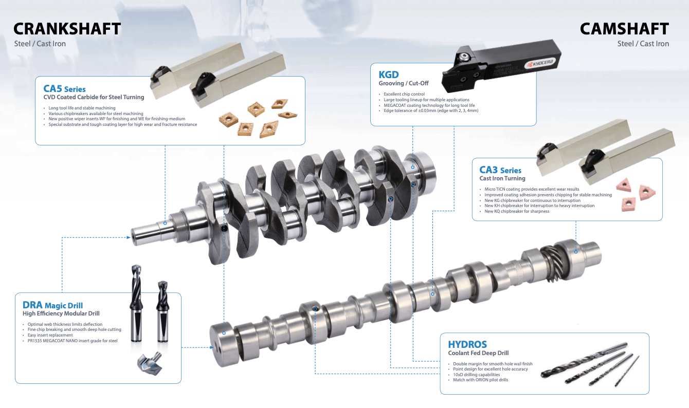
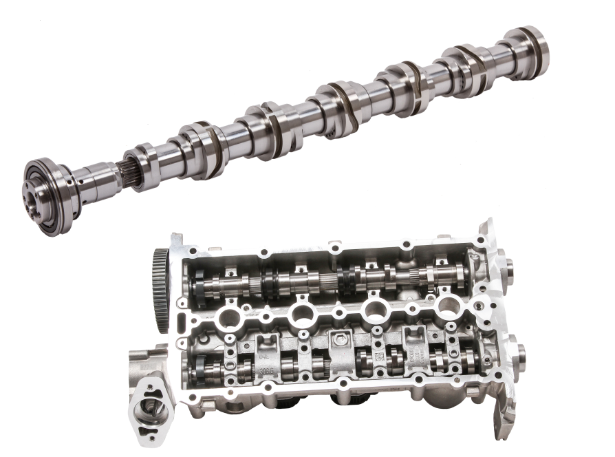
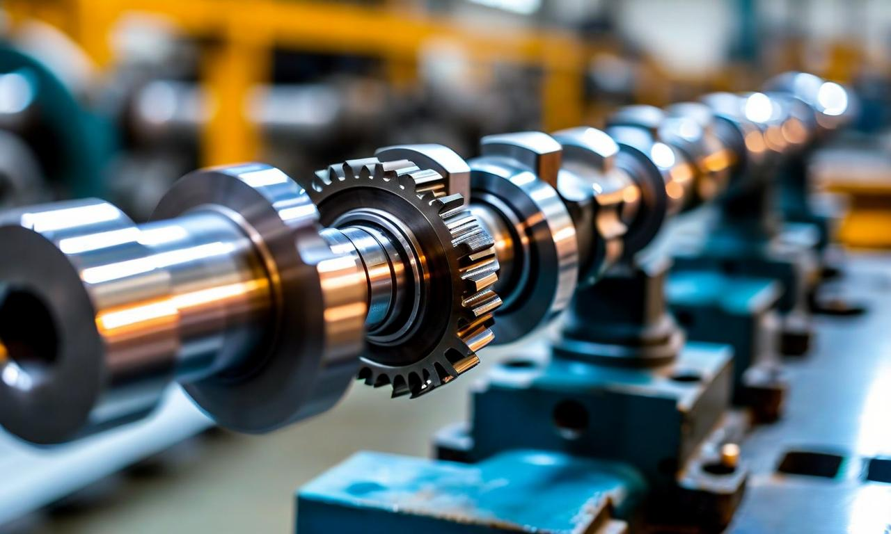
Every high-performance automotive engine has a core component: the camshaft. It acts as the “brain” of the valve train. It controls the timing and lift of engine valves. This directly impacts combustion efficiency, torque output, and overall engine performance. Advanced automotive engineering relies heavily on CNC (Computer Numerical Control) machining. CNC machining delivers unmatched precision and consistency for modern camshaft production. TOP Prototype is a leader in this field. It provides precision machining solutions that blend innovation and reliability for global automotive manufacturers.

Why CNC Machining Is Indispensable for Camshaft Production

Automotive camshaft manufacturing demands exceptional engineering precision. Camshafts have complex structures. They require micron-level tolerances, unlike standard mechanical components. Even small deviations cause problems. These include reduced efficiency, increased noise, or premature wear. Such flaws are unacceptable in today’s competitive market. CNC machining solves these challenges with unique advantages:

– Computerized control systems eliminate human error. They ensure consistent precision across all components.

– Multi-axis machining handles complex lobe profiles, journals, and keyways in one setup. This shortens production cycles.

– It adapts to diverse materials, from alloy steels to titanium. It meets the needs of different engine types.

TOP Prototype’s Expertise: Elevating CNC Camshaft Machining to New Heights

TOP Prototype has refined CNC camshaft machining into an art. It combines state-of-the-art equipment with decades of engineering experience. The company offers end-to-end solutions. These cover every critical production stage, from design to delivery. It prioritizes customization and quality.

1. Design Optimization & Material Selection

TOP Prototype’s engineers use advanced CAD simulation tools. They optimize camshaft profiles before machining starts. These profiles align with specific engine performance goals. They suit compact hybrids and high-performance racing engines alike. Material selection is equally strict. Camshafts must resist extreme temperatures and mechanical stress. TOP Prototype’s facilities handle various materials easily, including:

– High-strength alloy steels. They offer balanced durability and performance for mainstream vehicles.

– QT700 ductile iron. It suits heavy-duty engines needing superior load-bearing capacity.

– Premium billet steel and titanium alloys. They create lightweight, high-performance racing camshafts.

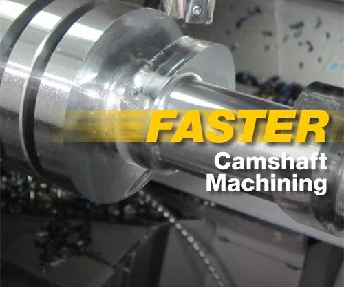
2. Advanced Machining & Grinding Technologies

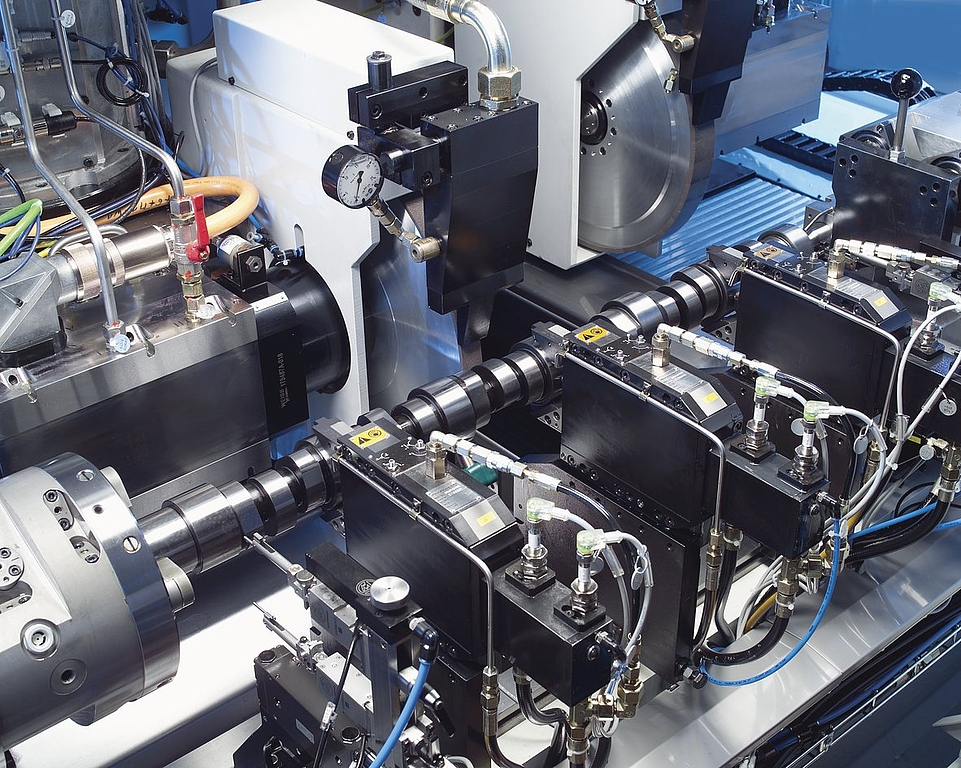
TOP Prototype’s core strength lies in its cutting-edge equipment and processes. It moves beyond traditional manual grinding. The company uses 5-axis CNC machining centers. These process multiple camshaft features at the same time. Key technological advantages include:

– 5-axis machining maintains tight tolerances of ±0.02mm for cam lobe profiles. This precision is critical for optimal valve timing.

– Adaptive grinding systems feature real-time in-process gauging. They make dynamic adjustments to correct material variations.

– It reduces setup times and material waste. It delivers cost-effective solutions without sacrificing precision.

3. Heat Treatment, Finishing & Quality Control


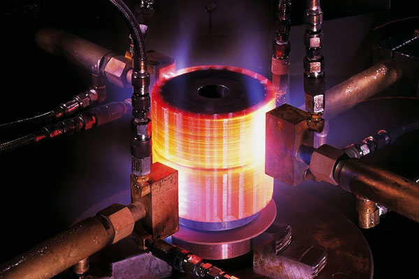
TOP Prototype enhances camshaft durability and wear resistance. It uses precision heat treatment processes. These include induction hardening and nitriding. They target high-friction areas like cam lobes. After heat treatment, final CNC grinding and polishing follow. They create mirror-like surfaces to reduce friction.

Quality control is non-negotiable for TOP Prototype. It conducts rigorous inspections at every stage:


-Raw material testing ensures compliance with mechanical property requirements.

– In-process monitoring uses advanced tools. It detects and corrects deviations in real time.

– Final verification relies on coordinate measuring machines (CMMs) and laser profilometers. It guarantees micron-level accuracy.

Adapting to the Future of Automotive Engineering

Electrification and hybridization are reshaping the automotive industry. Yet demand for precision camshafts remains stable. Even hybrid powertrains need camshafts. They optimize internal combustion engine performance. TOP Prototype has adapted to these changes. It invests in cutting-edge CNC technology. It also expands its engineering capabilities to support next-generation engine designs.

The company offers great flexibility. It handles low-volume prototype runs and high-volume production batches. This makes it a trusted partner for automotive manufacturers. These include startups developing innovative powertrains and established OEMs scaling production. Beyond technical expertise, TOP Prototype adopts a customer-centric approach. It offers customized solutions. These balance precision, cost, and lead time. This approach has earned it a reputation as a reliable industry leader.

Conclusion: TOP Prototype—Your Trusted Partner for Precision Camshaft Machining


The camshaft is small but critical. It powers the modern automotive engine. CNC machining enables its precision. TOP Prototype leads this industry. It delivers high-quality, precision-machined camshafts. These meet the most demanding automotive standards.

TOP Prototype provides end-to-end solutions. They cover material selection, design optimization, multi-axis machining, and rigorous quality control. These solutions ensure every camshaft performs optimally. For automotive manufacturers aiming to boost engine performance, TOP Prototype is the ideal partner. It offers CNC camshaft machining that combines precision, reliability, and innovation.

Let's Start A New Project Today

Latest Blog Posts

Check out the latest industry trends and take inspiration from our updated blogs, giving you a fresh insight to help boost your business.

Tapped Holes vs Threaded Holes – Differences and Comparison

Tapped Holes vs Threaded Holes – Differences and Comparison In mechanical manufacturing, assembly, and precision engineering, internal threaded holes serve as the “connective tissue” of components, enabling secure fastening, precise positioning, and stable load transmission. Tapped holes and threaded holes, two widely applied types of internal threaded structures, are often conflated due to their overlapping functional goals. Yet their divergence in processing principles, structural integrity, and practical performance is substantial—differences that directly affect product reliability, production costs, and service life. This article systematically distinguishes the two, enriches the discussion with industrial practices and material science facts, simplifies complex terminology, and reconstructs the logical framework to clarify their characteristics, advantages, and application boundaries for engineering practitioners. 1. Definitions and Core Structural Traits 1.1 Tapped Holes: Direct Thread Formation in Base Material A tapped hole is an internal threaded hole formed by the tapping process, where a specialized cutting tool (tap) cuts or forms threads on the inner wall of a pre-drilled pilot hole. Unlike indirect threading methods, tapped holes integrate threads directly into the workpiece’s base material—no auxiliary inserts or reinforcements are involved. Taps operate on a subtractive principle: they remove excess material from the pilot hole’s inner surface to form standardized thread profiles, such as metric (M series), unified coarse (UNC), or unified fine (UNF) threads, with precision grades ranging from 2B (general purpose) to 3B (high precision) for imperial threads. This integration with the base material means tapped holes’ performance is inherently tied to the workpiece’s material properties. For instance, in medium-carbon steel (e.g., 45# steel) or 6061 aluminum alloy—materials with moderate ductility and strength—tapped holes deliver reliable thread retention. They are widely adopted in scenarios where the workpiece itself can bear fastening loads, avoiding the need for additional components. 1.2 Threaded Holes: A Broad Category with Indirect Threading Dominance The term “threaded hole” is a generic concept encompassing all holes with internal threads, including tapped holes. In industrial practice, however, it primarily refers to holes where threads are formed indirectly—most commonly via threaded inserts. These inserts, made of high-strength materials like 304 stainless steel or titanium alloy, are installed into pre-drilled holes to provide the internal thread interface, decoupling thread performance from the workpiece’s base material. Beyond insert-based threading, threaded holes also include structures formed by thread rolling, casting, or injection molding. Thread rolling, for example, is used for high-volume production of ductile materials like copper or low-carbon steel, forming threads through plastic deformation rather than cutting. Cast or molded threaded holes are integral to composite parts (e.g., glass-fiber reinforced plastic) or plastic components, where threads are pre-designed in the mold to eliminate post-processing. 2. Core Differences in Processing Principles and Operations The fundamental gap between tapped holes and threaded holes lies in their thread formation mechanisms—each dictating processing efficiency, precision limits, and material applicability. Simplifying these mechanisms reveals why each is preferred in specific scenarios. 2.1 Tapped Holes: Two-Step Subtractive Processing Tapping follows a rigid two-step workflow: first, drilling a pilot hole with a diameter strictly matched to the target thread (e.g., a 6.8mm pilot hole for an M8×1.25 tap); second, cutting threads using a hand tap (for small batches or manual operations) or machine tap (for automated production on CNC lathes, milling machines, or dedicated tapping centers). Critical process parameters directly impact thread quality: tap speed (typically 10-30 m/min for steel, 20-50 m/min for aluminum), feed rate (matched to thread pitch to avoid thread distortion), and lubrication (cutting oil for ferrous metals, cutting fluid for non-ferrous metals to reduce friction and prevent burring). Brittle materials like gray cast iron (HT200) or zirconia ceramic require specialized spiral-flute taps to evacuate chips and avoid cracking, while ductile materials like copper demand straight-flute taps for smooth chip removal. 2.2 Threaded Holes: Indirect Formation with Diversified Methods Insert-based threaded holes, the most common type, follow a three-step process: drilling a hole matching the insert’s outer diameter (e.g., a 10.2mm hole for an M8 helical insert), installing the insert via pressing, self-tapping, or adhesive bonding, and verifying thread accuracy. Helical wire inserts (HeliCoils), for example, are coiled stainless steel wires with a diamond cross-section—when installed, they expand to lock into the pre-drilled hole, distributing fastening loads over a larger surface area to prevent thread stripping. Other threading methods for threaded holes have clear niche applications: thread rolling achieves higher thread strength (up to 30% higher than cut threads due to work hardening) and is used for high-volume parts like automotive bolts; casting/molding eliminates post-processing but is limited to parts with simple thread geometries, as complex threads may cause mold release issues. 3. Performance Comparison and Practical Application Scenarios Evaluating strength, precision, cost, and maintainability reveals the practical trade-offs between tapped holes and threaded holes. Grounded in industrial data and real-world cases, this comparison helps engineers make evidence-based selections. …

Analysis of Causes and Solutions of Surface Roughness Issues in CNC Machining

Analysis of Causes and Solutions of Surface Roughness Issues in CNC Machining In CNC machining, surface roughness is critical—it directly …

TOP Prototype CNC Customization Precision Machining Tailored Solutions for Global Industrial Innovation   The Art and Science of TOP Prototype CNC Customization   CNC customization blends engineering precision with creative …

Scroll to Top

Contact Us

Upload Your Files to Get Instant Quote and DFM Feedback
(Please attach 2D CAD drawings and 3D CAD models in any format including STEP,STP, IGES, DWG, PDF, STL, PDF, JPG , ZIP, RAR, etc