
Analysis of Causes and Solutions of Surface Roughness Issues in CNC Machining
In CNC machining, surface roughness is critical—it directly impacts the quality and functionality of machined parts. TOP Prototype, a leading ISO9001-certified rapid prototyping manufacturer in China with over 15 years of experience, knows that optimal surface finishes are non-negotiable. Surface roughness affects not just a part’s appearance, but also its performance: wear resistance, fatigue strength, and corrosion resistance. Drawing on TOP Prototype’s hands-on expertise, this article explores the causes of surface roughness in CNC machining and offers practical, proven solutions.
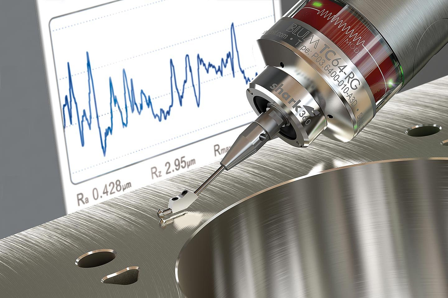
Surface roughness refers to small-scale irregularities on a machined part’s surface, measured as the average deviation from a perfectly smooth plane over a specific sampling length. Smooth surfaces are often required for parts with tight tolerances, good sealing, or low friction. However, achieving this is challenging due to various factors that disrupt the machining process—factors TOP Prototype has studied and addressed through years of practice.
Cutting tools wear down over time, leading to flank wear, crater wear, or edge chipping. A dull tool can’t cut material cleanly, resulting in rough edges and higher surface roughness. At TOP Prototype, machinists often see this in milling operations: a worn end-mill leaves uneven surfaces because it can’t shear material effectively. Flank wear (on the tool’s workpiece-facing side) increases friction, worsening surface irregularities.
Tool geometry—rake angle, clearance angle, nose radius—plays a key role in surface roughness. An improper rake angle, for example, fails to shear material efficiently. At TOP Prototype, machining soft aluminum with a too-small rake angle often pushes material instead of cutting it, causing deformation and rougher surfaces. A small nose radius also creates a more noticeable scallop effect, raising surface roughness values.
Cutting speed, feed rate, and depth of cut directly affect surface roughness. A high feed rate removes more material per tool pass, leaving larger uncut chips and rougher finishes—something TOP Prototype avoids by adjusting parameters for each project. A low cutting speed for hard materials reduces efficiency, causing plastic deformation and rougher surfaces. TOP Prototype’s engineers note that balancing these parameters is key to smooth finishes.
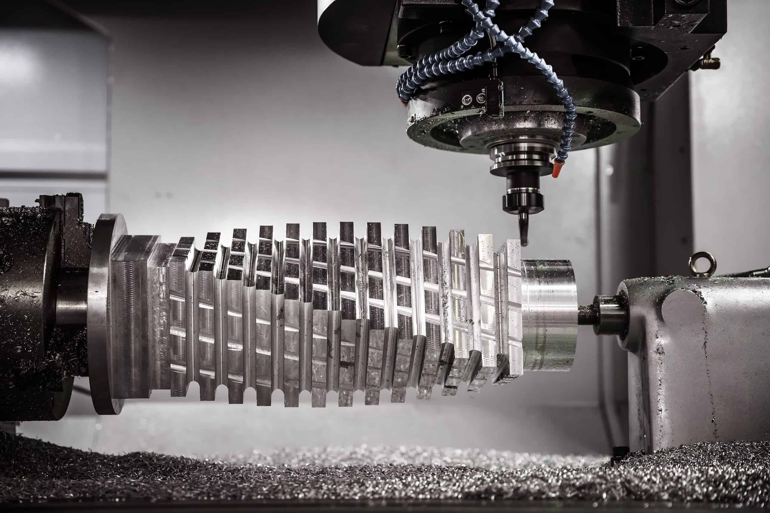
Vibrations (from unbalanced tools, poor system rigidity, or resonance) are a major cause of surface roughness. At TOP Prototype, high-speed machining with an unbalanced spindle transfers vibrations to the tool and workpiece, creating wavy surfaces. Loose workpiece clamping also causes vibrations, leading to poor finishes. TOP Prototype addresses this by prioritizing system rigidity in every setup.
Workpiece material properties—hardness and ductility—impact surface roughness. Soft, ductile materials like low-carbon steel are prone to plastic deformation. At TOP Prototype, unoptimized cutting of low-carbon steel can cause material to smear on the surface, creating roughness. Harder materials like hardened steel wear tools faster, which also leads to rough surfaces.
Internal voids, impurities, or uneven grain structures in materials cause surface roughness. At TOP Prototype, metal alloys with hard inclusions can make tools vibrate or chip when encountered, leaving rough surfaces. This is why TOP Prototype strictly controls material quality before machining.
CNC machining generates significant heat, and coolant is vital for heat dissipation and lubrication. At TOP Prototype, ineffective coolant or insufficient flow leads to overheating in the cutting zone, accelerating tool wear and material deformation. Poor lubrication increases tool-workpiece friction, resulting in rougher surfaces.
Coolant contaminated with chips, debris, or foreign substances worsens surface roughness. At TOP Prototype, a poorly maintained coolant filter lets contaminants circulate back to the cutting zone. These particles scratch the workpiece and reduce coolant effectiveness, leading to rougher finishes.
TOP Prototype emphasizes regular tool checks before and after each operation. Machinists visually inspect end-mill cutting edges for chipping or excessive wear, replacing tools promptly when they reach wear limits. This simple step drastically reduces surface roughness caused by worn tools.
TOP Prototype’s engineers select tools based on material, required finish, and machining operation. For hard materials like titanium, they use specialized carbide-coated tools with proper geometries—designed to handle high forces and temperatures, ensuring smooth surfaces.
TOP Prototype uses advanced machining simulation software to optimize parameters. By inputting material, tool, and operation details, the software recommends the best cutting speed, feed rate, and depth of cut. Engineers fine-tune these through testing to balance efficiency and surface finish—for example, optimizing aluminum part machining to get the smoothest possible surface.
To reduce vibrations, TOP Prototype ensures machines are properly grounded and leveled, and uses well-designed workholding fixtures. For lathe operations, a secure chuck minimizes workpiece vibration. Vibration-damping materials in machine structures or tool holders also absorb vibrations, leading to smoother finishes.
Pre-machining treatments are often performed for optimal results. For highly ductile materials, annealing reduces ductility and relieves internal stresses, preventing warping and surface roughness during machining.
Materials are sourced from reliable suppliers with strict quality checks in place, and those with inhomogeneities are rejected. This ensures material-related surface roughness issues are minimized from the start.
Coolants are selected based on the workpiece material and machining operation. Water-soluble coolants are used for aluminum for excellent cooling and lubrication, while synthetic coolants are adopted for high-temperature alloys. The chemical composition of coolants is also optimized to ensure compatibility with the workpiece material and reliable corrosion protection.
Coolant filters are cleaned or replaced on a regular basis, with concentration monitored and adjusted as needed and temperature kept under strict control. Proper coolant maintenance guarantees effective cooling and lubrication, leading to improved surface finishes.
Surface roughness in CNC machining stems from tool, process, material, and coolant factors. With over 15 years of experience, TOP Prototype has developed a comprehensive approach to address these issues: strict tool management, process optimization, material quality control, and proactive coolant maintenance. These steps let TOP Prototype consistently deliver high-quality surface finishes, improving product quality and machining efficiency. As demand for precision parts grows, addressing surface roughness remains critical—and TOP Prototype continues to lead the way with practical, results-driven solutions.