• Home
  • 未分类
  • Precision at the Core: CNC Machining for Automotive Engine Blocks by TOP Prototype

Precision at the Core: CNC Machining for Automotive Engine Blocks by TOP Prototype

Precision at the Core: CNC Machining for Automotive Engine Blocks by TOP Prototype

Precision at the Core: CNC Machining for Automotive Engine Blocks by TOP Prototype

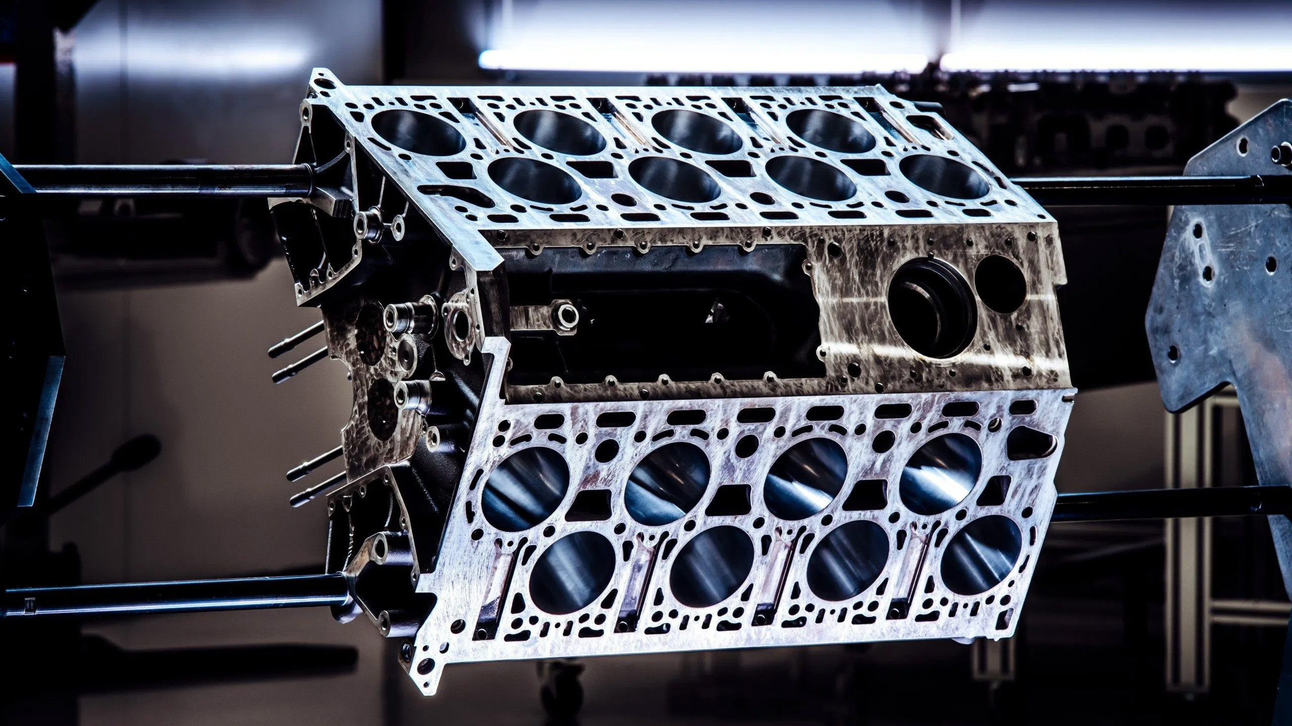
The engine block is the backbone of every automotive powertrain. It houses critical components, such as cylinders, crankshafts, and pistons. It bears extreme temperatures, pressure, and mechanical stress. Its precision directly determines engine efficiency, durability, and performance. Modern automotive manufacturing relies on CNC (Computer Numerical Control) machining. This technology is irreplaceable for engine block production. TOP Prototype is a global leader in precision machining. It uses advanced CNC solutions to redefine engine block manufacturing standards. It combines accuracy, efficiency, and innovation for automotive clients worldwide.


Why CNC Machining Is Critical for Engine Block Production

Automotive engine blocks have complex structures. These include cylinder bores, water jackets, oil passages, and bolt holes. They require ultra-strict tolerances. A 0.01mm deviation can cause oil leaks. It may also reduce combustion efficiency or lead to premature engine failure. CNC machining solves these challenges with unmatched advantages. Tangible industry data supports these benefits:
·It eliminates human error. It reduces defect rates to less than 0.03%. This is a 90% improvement over traditional manual machining.
·Multi-axis CNC centers cut production cycles by 35% on average. Smart manufacturing benchmarks verify this figure.
·It ensures consistent precision across batches. Key features like cylinder bores have dimensional repeatability within ±0.005mm.


TOP Prototype’s CNC Engine Block Machining: Technology & Data-Driven Excellence

TOP Prototype has refined its CNC engine block machining capabilities. It draws on decades of engineering practice and technological investment. The company integrates state-of-the-art equipment, premium material expertise, and rigorous quality control. It delivers components that meet the most demanding automotive standards. Its solutions cover the entire production process, from raw material selection to final inspection.

1. Material Mastery for High-Performance Engine Blocks
Engine block materials must balance strength, lightness, and heat resistance. TOP Prototype specializes in processing various high-grade materials. It has proven results in material optimization:

– High-strength ductile iron (QT900-2): TOP Prototype’s precision machining reduces component weight by up to 30%. It also boosts yield strength by 114% compared to conventional RUT400 vermicular iron.

– Aluminum alloys: The company’s CNC processes raise material utilization rate to 92%. This minimizes waste for lightweight hybrid vehicle engine blocks.
– Nickel-plated ceramic composites: For high-performance engines, TOP Prototype applies CNC-finished plating. This improves wear resistance by 40%.

2. Advanced CNC Processes with Quantifiable Precision
TOP Prototype’s core competitiveness lies in its 5-axis and 6-axis CNC machining centers. They pair with intelligent process control. Concrete data supports its key technological advantages:

– 5-axis simultaneous machining: It completes cylinder bore, water jacket, and oil passage processing in one setup. It cuts setup time by 60%. It ensures bolt hole positional accuracy within ±0.015mm.

– Adaptive machining systems: Real-time data monitoring adjusts cutting parameters dynamically. It reduces tool wear by 25%. It extends tool lifespan by 30%.

– High-speed CNC milling: Spindle speeds reach up to 20,000 rpm. It achieves a surface roughness (Ra) of 0.8μm for cylinder bores. This optimizes piston movement efficiency.

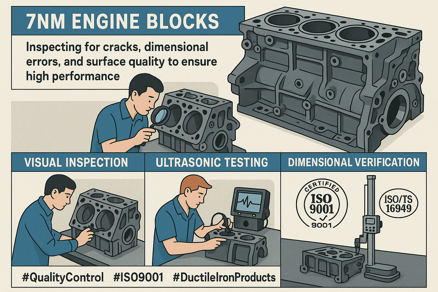
3.Strict Quality Control: Zero-Defect Commitment

TOP Prototype implements a three-stage quality control system.

Advanced testing equipment ensures 100% traceability for every engine block:
·Raw material inspection: Tensile strength and microstructure testing eliminate substandard materials. Material qualification has a 100% pass rate.
·In-process monitoring: Laser profilometers and coordinate measuring machines (CMMs) conduct 120+ dimensional checks per component. They detect deviations in 0.5 seconds.
·Final verification: X-ray inspection identifies internal defects like shrinkage holes. It ensures a zero-defect delivery rate for mass production batches.

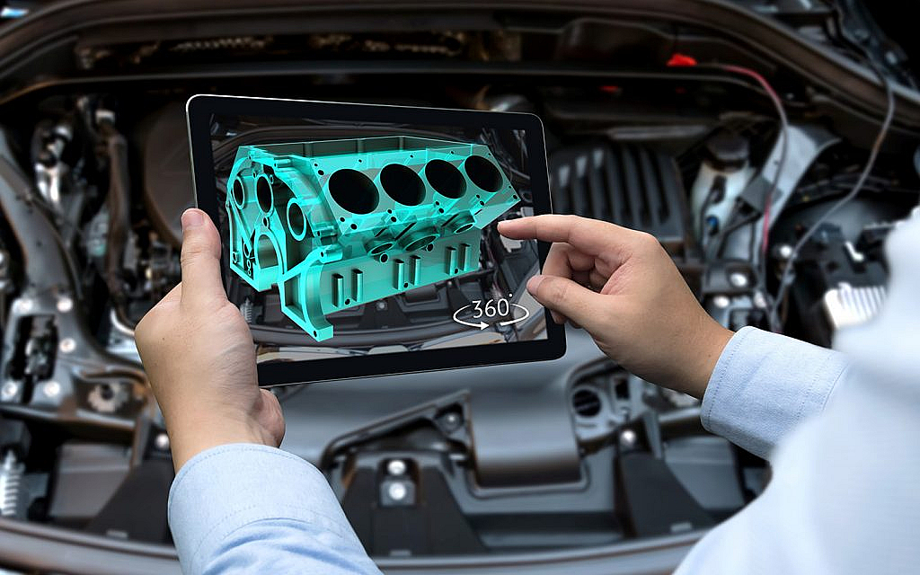
TOP Prototype: Adapting to the Future of Automotive Engineering

Electrification and hybridization are reshaping the industry. Engine block designs demand greater precision and versatility. TOP Prototype has adapted proactively. It delivers measurable results for clients:

The company’s flexible production lines handle low-volume prototypes and high-volume production. The minimum batch size for prototypes is 5 units. Annual production capacity reaches 100,000 units. For hybrid engine blocks, TOP Prototype’s CNC solutions shorten R&D cycles by 30%. They also reduce per-unit manufacturing costs by 12.6%. Its global service network supports clients in Europe, Southeast Asia, and North America. On-time delivery rates exceed 98%.

TOP Prototype adopts a customer-centric approach. It also offers customized design optimization. Its engineers use CAD simulation to refine engine block structures. This improves heat dissipation efficiency by 18%. It reduces fuel consumption for end-users.


The engine block is the heart of automotive performance. CNC machining enables its precision. TOP Prototype stands out in the industry with data-driven excellence. It excels in material optimization, advanced machining, and strict quality control. Its ability to deliver lightweight, high-strength engine blocks with consistent precision is unmatched. This makes it a trusted partner for leading automakers and startups alike.

Automotive manufacturers aim to enhance engine performance, reduce costs, and accelerate time-to-market. For them, TOP Prototype offers end-to-end CNC machining solutions. It focuses on innovation, quality, and measurable results. TOP Prototype continues to set new benchmarks in automotive engine block manufacturing.

Let's Start A New Project Today

Latest Blog Posts

Check out the latest industry trends and take inspiration from our updated blogs, giving you a fresh insight to help boost your business.

Tapped Holes vs Threaded Holes – Differences and Comparison

Tapped Holes vs Threaded Holes – Differences and Comparison In mechanical manufacturing, assembly, and precision engineering, internal threaded holes serve as the “connective tissue” of components, enabling secure fastening, precise positioning, and stable load transmission. Tapped holes and threaded holes, two widely applied types of internal threaded structures, are often conflated due to their overlapping functional goals. Yet their divergence in processing principles, structural integrity, and practical performance is substantial—differences that directly affect product reliability, production costs, and service life. This article systematically distinguishes the two, enriches the discussion with industrial practices and material science facts, simplifies complex terminology, and reconstructs the logical framework to clarify their characteristics, advantages, and application boundaries for engineering practitioners. 1. Definitions and Core Structural Traits 1.1 Tapped Holes: Direct Thread Formation in Base Material A tapped hole is an internal threaded hole formed by the tapping process, where a specialized cutting tool (tap) cuts or forms threads on the inner wall of a pre-drilled pilot hole. Unlike indirect threading methods, tapped holes integrate threads directly into the workpiece’s base material—no auxiliary inserts or reinforcements are involved. Taps operate on a subtractive principle: they remove excess material from the pilot hole’s inner surface to form standardized thread profiles, such as metric (M series), unified coarse (UNC), or unified fine (UNF) threads, with precision grades ranging from 2B (general purpose) to 3B (high precision) for imperial threads. This integration with the base material means tapped holes’ performance is inherently tied to the workpiece’s material properties. For instance, in medium-carbon steel (e.g., 45# steel) or 6061 aluminum alloy—materials with moderate ductility and strength—tapped holes deliver reliable thread retention. They are widely adopted in scenarios where the workpiece itself can bear fastening loads, avoiding the need for additional components. 1.2 Threaded Holes: A Broad Category with Indirect Threading Dominance The term “threaded hole” is a generic concept encompassing all holes with internal threads, including tapped holes. In industrial practice, however, it primarily refers to holes where threads are formed indirectly—most commonly via threaded inserts. These inserts, made of high-strength materials like 304 stainless steel or titanium alloy, are installed into pre-drilled holes to provide the internal thread interface, decoupling thread performance from the workpiece’s base material. Beyond insert-based threading, threaded holes also include structures formed by thread rolling, casting, or injection molding. Thread rolling, for example, is used for high-volume production of ductile materials like copper or low-carbon steel, forming threads through plastic deformation rather than cutting. Cast or molded threaded holes are integral to composite parts (e.g., glass-fiber reinforced plastic) or plastic components, where threads are pre-designed in the mold to eliminate post-processing. 2. Core Differences in Processing Principles and Operations The fundamental gap between tapped holes and threaded holes lies in their thread formation mechanisms—each dictating processing efficiency, precision limits, and material applicability. Simplifying these mechanisms reveals why each is preferred in specific scenarios. 2.1 Tapped Holes: Two-Step Subtractive Processing Tapping follows a rigid two-step workflow: first, drilling a pilot hole with a diameter strictly matched to the target thread (e.g., a 6.8mm pilot hole for an M8×1.25 tap); second, cutting threads using a hand tap (for small batches or manual operations) or machine tap (for automated production on CNC lathes, milling machines, or dedicated tapping centers). Critical process parameters directly impact thread quality: tap speed (typically 10-30 m/min for steel, 20-50 m/min for aluminum), feed rate (matched to thread pitch to avoid thread distortion), and lubrication (cutting oil for ferrous metals, cutting fluid for non-ferrous metals to reduce friction and prevent burring). Brittle materials like gray cast iron (HT200) or zirconia ceramic require specialized spiral-flute taps to evacuate chips and avoid cracking, while ductile materials like copper demand straight-flute taps for smooth chip removal. 2.2 Threaded Holes: Indirect Formation with Diversified Methods Insert-based threaded holes, the most common type, follow a three-step process: drilling a hole matching the insert’s outer diameter (e.g., a 10.2mm hole for an M8 helical insert), installing the insert via pressing, self-tapping, or adhesive bonding, and verifying thread accuracy. Helical wire inserts (HeliCoils), for example, are coiled stainless steel wires with a diamond cross-section—when installed, they expand to lock into the pre-drilled hole, distributing fastening loads over a larger surface area to prevent thread stripping. Other threading methods for threaded holes have clear niche applications: thread rolling achieves higher thread strength (up to 30% higher than cut threads due to work hardening) and is used for high-volume parts like automotive bolts; casting/molding eliminates post-processing but is limited to parts with simple thread geometries, as complex threads may cause mold release issues. 3. Performance Comparison and Practical Application Scenarios Evaluating strength, precision, cost, and maintainability reveals the practical trade-offs between tapped holes and threaded holes. Grounded in industrial data and real-world cases, this comparison helps engineers make evidence-based selections. …

Analysis of Causes and Solutions of Surface Roughness Issues in CNC Machining

Analysis of Causes and Solutions of Surface Roughness Issues in CNC Machining In CNC machining, surface roughness is critical—it directly …

TOP Prototype CNC Customization Precision Machining Tailored Solutions for Global Industrial Innovation   The Art and Science of TOP Prototype CNC Customization   CNC customization blends engineering precision with creative …

Scroll to Top

Contact Us

Upload Your Files to Get Instant Quote and DFM Feedback
(Please attach 2D CAD drawings and 3D CAD models in any format including STEP,STP, IGES, DWG, PDF, STL, PDF, JPG , ZIP, RAR, etc