All You Need to Know about SLA Manufacturing in the Medical Industry

All You Need to Know about SLA Manufacturing in the Medical Industry

In the world of 3D printing, SLA manufacturing holds a special place, especially in industries where extreme precision and fine detail are critical. One specific field is the medical industry, where precise, tailored, and biocompatible components may have a life-changing impact.

Among the numerous additive manufacturing methods, SLA manufacturing has become a preferred method for producing complex medical components with high-resolution and smooth surface finishes.

So, in this article, we’ll take a deeper look at SLA manufacturing in the medical industry, discussing its working principles, benefits, limits, and practical applications.

SLA Manufacturing Parts

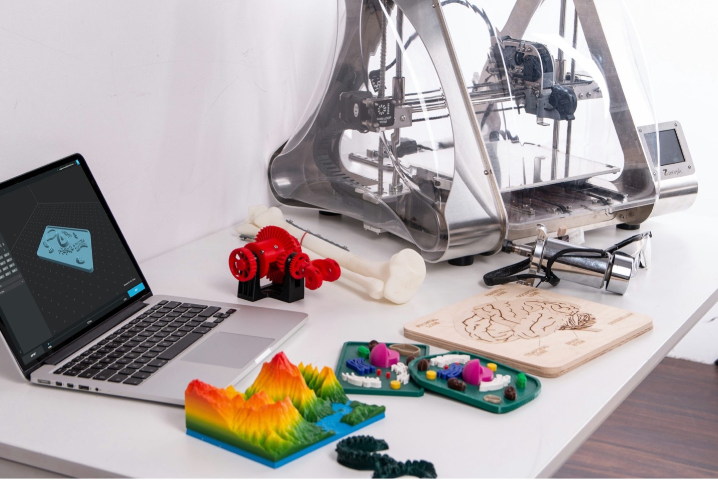
(Copyright Photo from: https://unsplash.com/photos/macbook-pro-beside-3d-printer-FB1vd3XT_zQ)

What Is SLA Manufacturing?

SLA manufacturing, also known as Stereolithography or SLA additive manufacturing, is one of the first and most advanced 3D printing processes. It is well-known for making high-precision prototypes and end-use parts with excellent details. The process employs photopolymerization, a method in which a liquid resin is selectively cured layer by layer using a UV laser.

How Does SLA Manufacturing Work?

The SLA process starts with a digital 3D model. A UV laser beam traces the pattern onto the surface of a vat containing liquid resin. When exposed to light, the resin hardens instantaneously, and the platform slowly lowers to allow the next layer to cure on top. This continues layer by layer until the entire item is produced. As a result, the process produces highly detailed components with smooth surfaces, making it ideal for delicate medical applications.

Pros and Cons of SLA Manufacturing in the Medical Industry

Like any technology, SLA manufacturing offers several advantages. However, it also has a few limitations that should be considered when applied to the medical industry. Here’s the breakdown:

SLA Technology
SLA Technology

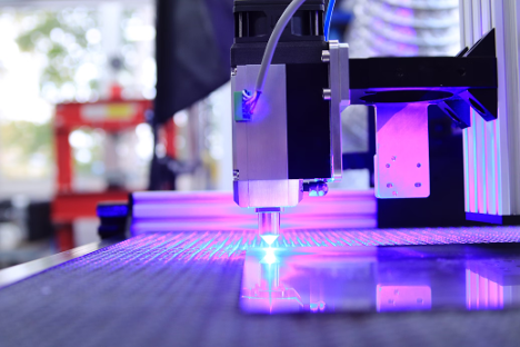
(Copyright Photo from: https://unsplash.com/photos/purple-and-white-led-light-KshEaH06rV8)

Pros

  • Exceptional Precision: SLA can achieve very fine resolutions, perfect for intricate anatomical structures and detailed prototypes.
  • Smooth Surface Finish: Unlike many other additive processes, SLA parts require minimal post-processing.
  • Customizability: Ideal for patient-specific applications such as prosthetics or surgical models.
  • Fast Turnaround: SLA rapid prototyping allows for faster iterations for design validation or pre-surgical planning.

Cons

  • Material Selection Limitations: SLA manufacturing uses resins, which can be photopolymerized. Other materials, like ABS or Nylon, would not be used because of non-photopolymerization.
  • Degraded under the Sunlight: It is not recommended to use it for long-term outdoor exposure, although it is manufactured by UV lasers.

Applications of SLA Manufacturing in the Medical Industry

Though there are some disadvantages, the versatility and precision of SLA additive manufacturing make it a useful tool in various critical medical applications, such as:

1.    Prosthetics and Orthotics

SLA allows for the creation of highly personalized prosthetics and orthotic devices tailored to individual anatomy. Its high precision ensures a snug fit and enhanced patient comfort.\

SLA Manufacturing in Medical Industry
SLA Manufacturing for Prosthetics and Orthotics

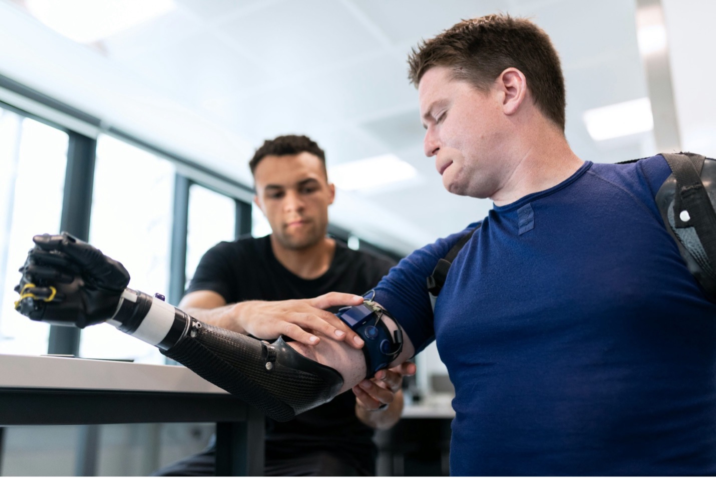
(Copyright Photo from: https://unsplash.com/photos/man-in-blue-crew-neck-shirt-holding-black-smartphone-J0XncLhc0vY)
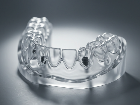
2.    Surgical Guides

Custom surgical guides allow surgeons to execute treatments with improved accuracy and safety. SLA’s fine resolution guarantees that the guides are properly contoured to fit the patient’s anatomy, reducing surgical mistakes.

Dental SLA Manufacturing Part

3.    Anatomical Models

SLA manufacturing produces realistic anatomical models that help with medical training, surgical planning, and patient communication. These models offer lifelike textures and visual clarity to better understand complex conditions.

SLA Manufacturing in Anatomical Application

TOP Prototype: Provide Reliable SLA Manufacturing Production

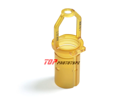
At TOP Prototype, we understand the significance of precision and dependability in medical production. For that reason, our SLA manufacturing service produces high-resolution, smooth-finished prototypes and working models that fulfill the demanding medical industry standards.

As part of our SLA rapid prototyping solutions, we offer the following:

  • Fast turnaround times to support tight project schedules
  • A variety of medical-grade materials for specialized needs
  • 24/7 detailed support for engineering
  • Scalable production for both one-off prototypes and small-batch manufacturing

Whether you’re developing custom surgical tools or complex anatomical models, TOP Prototype combines speed and quality to help you bring your vision to life safely and efficiently.

Top Prototype SLA Parts

Conclusion

SLA manufacturing has become an essential tool in the advancement of the contemporary medical industry. SLA additive manufacturing, with its unrivaled precision, flawless finishes, and quick delivery, is changing the way healthcare professionals design, plan, and execute medical procedures. And with the help of an experienced partner like TOP Prototype, you can keep your medical initiatives ahead of the competition.

Reach out to our experts by contact form to learn more!

Let's Start A New Project Today

Latest Blog Posts

Check out the latest industry trends and take inspiration from our updated blogs, giving you a fresh insight to help boost your business.

CNC Machining of Aluminum: Properties and Applications by TOP Prototype

CNC Machining of Aluminum: Properties and Applications by TOP Prototype Aluminum, with its unique combination of physical and mechanical properties, …

Tapped Holes vs Threaded Holes – Differences and Comparison

Tapped Holes vs Threaded Holes – Differences and Comparison In mechanical manufacturing, assembly, and precision engineering, internal threaded holes serve as the “connective tissue” of components, enabling secure fastening, precise positioning, and stable load transmission. Tapped holes and threaded holes, two widely applied types of internal threaded structures, are often conflated due to their overlapping functional goals. Yet their divergence in processing principles, structural integrity, and practical performance is substantial—differences that directly affect product reliability, production costs, and service life. This article systematically distinguishes the two, enriches the discussion with industrial practices and material science facts, simplifies complex terminology, and reconstructs the logical framework to clarify their characteristics, advantages, and application boundaries for engineering practitioners. 1. Definitions and Core Structural Traits 1.1 Tapped Holes: Direct Thread Formation in Base Material A tapped hole is an internal threaded hole formed by the tapping process, where a specialized cutting tool (tap) cuts or forms threads on the inner wall of a pre-drilled pilot hole. Unlike indirect threading methods, tapped holes integrate threads directly into the workpiece’s base material—no auxiliary inserts or reinforcements are involved. Taps operate on a subtractive principle: they remove excess material from the pilot hole’s inner surface to form standardized thread profiles, such as metric (M series), unified coarse (UNC), or unified fine (UNF) threads, with precision grades ranging from 2B (general purpose) to 3B (high precision) for imperial threads. This integration with the base material means tapped holes’ performance is inherently tied to the workpiece’s material properties. For instance, in medium-carbon steel (e.g., 45# steel) or 6061 aluminum alloy—materials with moderate ductility and strength—tapped holes deliver reliable thread retention. They are widely adopted in scenarios where the workpiece itself can bear fastening loads, avoiding the need for additional components. 1.2 Threaded Holes: A Broad Category with Indirect Threading Dominance The term “threaded hole” is a generic concept encompassing all holes with internal threads, including tapped holes. In industrial practice, however, it primarily refers to holes where threads are formed indirectly—most commonly via threaded inserts. These inserts, made of high-strength materials like 304 stainless steel or titanium alloy, are installed into pre-drilled holes to provide the internal thread interface, decoupling thread performance from the workpiece’s base material. Beyond insert-based threading, threaded holes also include structures formed by thread rolling, casting, or injection molding. Thread rolling, for example, is used for high-volume production of ductile materials like copper or low-carbon steel, forming threads through plastic deformation rather than cutting. Cast or molded threaded holes are integral to composite parts (e.g., glass-fiber reinforced plastic) or plastic components, where threads are pre-designed in the mold to eliminate post-processing. 2. Core Differences in Processing Principles and Operations The fundamental gap between tapped holes and threaded holes lies in their thread formation mechanisms—each dictating processing efficiency, precision limits, and material applicability. Simplifying these mechanisms reveals why each is preferred in specific scenarios. 2.1 Tapped Holes: Two-Step Subtractive Processing Tapping follows a rigid two-step workflow: first, drilling a pilot hole with a diameter strictly matched to the target thread (e.g., a 6.8mm pilot hole for an M8×1.25 tap); second, cutting threads using a hand tap (for small batches or manual operations) or machine tap (for automated production on CNC lathes, milling machines, or dedicated tapping centers). Critical process parameters directly impact thread quality: tap speed (typically 10-30 m/min for steel, 20-50 m/min for aluminum), feed rate (matched to thread pitch to avoid thread distortion), and lubrication (cutting oil for ferrous metals, cutting fluid for non-ferrous metals to reduce friction and prevent burring). Brittle materials like gray cast iron (HT200) or zirconia ceramic require specialized spiral-flute taps to evacuate chips and avoid cracking, while ductile materials like copper demand straight-flute taps for smooth chip removal. 2.2 Threaded Holes: Indirect Formation with Diversified Methods Insert-based threaded holes, the most common type, follow a three-step process: drilling a hole matching the insert’s outer diameter (e.g., a 10.2mm hole for an M8 helical insert), installing the insert via pressing, self-tapping, or adhesive bonding, and verifying thread accuracy. Helical wire inserts (HeliCoils), for example, are coiled stainless steel wires with a diamond cross-section—when installed, they expand to lock into the pre-drilled hole, distributing fastening loads over a larger surface area to prevent thread stripping. Other threading methods for threaded holes have clear niche applications: thread rolling achieves higher thread strength (up to 30% higher than cut threads due to work hardening) and is used for high-volume parts like automotive bolts; casting/molding eliminates post-processing but is limited to parts with simple thread geometries, as complex threads may cause mold release issues. 3. Performance Comparison and Practical Application Scenarios Evaluating strength, precision, cost, and maintainability reveals the practical trade-offs between tapped holes and threaded holes. Grounded in industrial data and real-world cases, this comparison helps engineers make evidence-based selections. …

Analysis of Causes and Solutions of Surface Roughness Issues in CNC Machining

Analysis of Causes and Solutions of Surface Roughness Issues in CNC Machining In CNC machining, surface roughness is critical—it directly …

Scroll to Top

Contact Us

Upload Your Files to Get Instant Quote and DFM Feedback
(Please attach 2D CAD drawings and 3D CAD models in any format including STEP,STP, IGES, DWG, PDF, STL, PDF, JPG , ZIP, RAR, etc