Everything You Need to Know about Multi-Axis Machining

Everything You Need to Know about Multi-Axis Machining

CNC machining has come a long way over the years, from basic 2D cutting to advanced multi-axis machining that handles complex shapes with high precision and speed.

As product designs get more advanced, multi-axis machining plays a key role in meeting modern manufacturing needs.

That said, in this blog, we’ll explain the basics, main components, types, and why it matters for today’s high-precision production.

CNC machining
CNC machining 

Key Components of Multi-Axis Machining Systems  

Before we dive into the different types of machining, it’s important to first understand what makes up a multi-axis machining system. Here are the key components:

1.    Multi-axis

Multi-axis refers to the number of possible movement directions for a cutting tool or workpiece. Traditional 3-axis systems use the X, Y, and Z axes, while newer machines can use rotating axes (A, B, or C) to provide additional flexibility of movement and access to complicated surfaces.

2.    Spindles

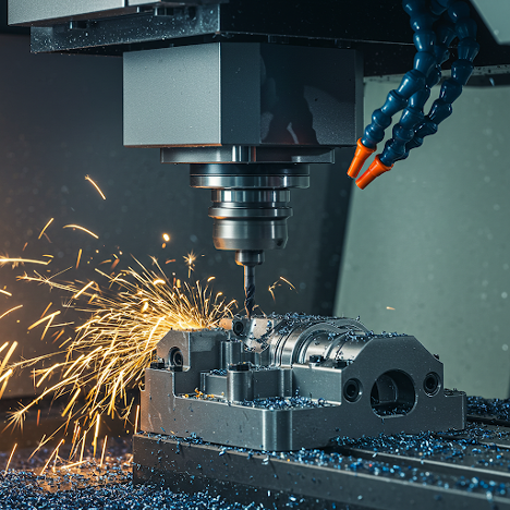
The spindle is the heart of the machine, holding and rotating the cutting tool. High-speed, high-torque spindles enable effective material removal, which is particularly significant in sophisticated multi-axis milling operations.

3.    Cutting Tools

Modern multi-axis machines employ a wide range of cutting tools specialized for specific activities such as drilling, milling, and contouring. These tools must endure high-speed cutting while maintaining constant precision throughout the manufacturing cycle.

4.    CNC Control Panel

In CNC machining, the CNC controller turns digital designs into physical actions. It coordinates tool trajectories, speeds, and motions across all dimensions to provide high-precision results with minimum human interaction.

metal CNC machining parts

Types of Multi-Axis CNC Machining

Now, let’s move on to the different types of multi-axis machining systems and break down each of them:

·        3-axis CNC Machining

The 3-axis CNC machining technique is considered to be the most basic type of CNC machining, which operates on the X, Y, and Z axes. While it works well for basic geometries, it has limits when dealing with intricate undercuts or curved surfaces.

·        4-axis CNC Machining

This option adds a rotating axis (usually the A-axis), allowing operations to be performed on several sides of a workpiece without the need for human repositioning. This increases efficiency and simplifies the handling of complex parts.

·        5-axis CNC machining

5-axis systems are a game changer in multi-axis machining, allowing movement along X, Y, and Z, as well as rotation along two extra axes (A and B). This improves access to complex geometry while substantially reducing setup times. It’s considered to be the gold standard in high-precision industries like aerospace, medical, and automotive manufacturing.

·        3+2 axis CNC machining

This approach, also known as positional 5-axis machining, involves locking the rotating axes at specified angles while milling. Unlike simultaneous 5-axis CNC machining services, this method is more suited to objects that require milling from several angles but do not require continuous rotation while cutting.

5-Axis vs. 3+2 Axis CNC Machining: What’s the Difference?

While both approaches outperform older methods, there is a major difference between 5-axis CNC machining services and 3+2-axis machining. Here’s the difference:

  • Simultaneous 5-axis Machining: All five axes move simultaneously during cutting. This enables smooth contouring of complex surfaces and reduces tool wear by maintaining optimal cutting angles.
  • 3+2 Axis Machining: The workpiece is slanted into place (by two rotating axes) and then machined with the standard three linear axes. It is easier and more cost-effective, but it lacks the fluidity and precision of genuine 5-axis machining.

All that being said, when high surface quality, complex geometry, and time efficiency matter, 5-axis machining services are the superior choice.

The TOP Prototype’s 5-Axis CNC Machining Services     

At TOP Prototype, we know complex parts need advanced solutions. That’s why our 5-axis CNC machining meets today’s demanding manufacturing needs. With up to 42-inch rod length, whether you need precise aerospace parts, strong automotive components, or custom prototypes, Top Prototype can provide fast and flexible solutions using advanced 5-axis technology.

Multi-axis CNC manufacturing
Customized CNC machining part

Conclusion

As performance standards rise and product designs get more complex, multi-axis machining stands out as a key tool for innovation and efficiency. When you partner with TOP Prototype, you get a trusted partner equipped with advanced multi-axis machining capabilities.

Please contact us directly to turn your designs into reality today.

Let's Start A New Project Today

Latest Blog Posts

Check out the latest industry trends and take inspiration from our updated blogs, giving you a fresh insight to help boost your business.

Tapped Holes vs Threaded Holes – Differences and Comparison

Tapped Holes vs Threaded Holes – Differences and Comparison In mechanical manufacturing, assembly, and precision engineering, internal threaded holes serve as the “connective tissue” of components, enabling secure fastening, precise positioning, and stable load transmission. Tapped holes and threaded holes, two widely applied types of internal threaded structures, are often conflated due to their overlapping functional goals. Yet their divergence in processing principles, structural integrity, and practical performance is substantial—differences that directly affect product reliability, production costs, and service life. This article systematically distinguishes the two, enriches the discussion with industrial practices and material science facts, simplifies complex terminology, and reconstructs the logical framework to clarify their characteristics, advantages, and application boundaries for engineering practitioners. 1. Definitions and Core Structural Traits 1.1 Tapped Holes: Direct Thread Formation in Base Material A tapped hole is an internal threaded hole formed by the tapping process, where a specialized cutting tool (tap) cuts or forms threads on the inner wall of a pre-drilled pilot hole. Unlike indirect threading methods, tapped holes integrate threads directly into the workpiece’s base material—no auxiliary inserts or reinforcements are involved. Taps operate on a subtractive principle: they remove excess material from the pilot hole’s inner surface to form standardized thread profiles, such as metric (M series), unified coarse (UNC), or unified fine (UNF) threads, with precision grades ranging from 2B (general purpose) to 3B (high precision) for imperial threads. This integration with the base material means tapped holes’ performance is inherently tied to the workpiece’s material properties. For instance, in medium-carbon steel (e.g., 45# steel) or 6061 aluminum alloy—materials with moderate ductility and strength—tapped holes deliver reliable thread retention. They are widely adopted in scenarios where the workpiece itself can bear fastening loads, avoiding the need for additional components. 1.2 Threaded Holes: A Broad Category with Indirect Threading Dominance The term “threaded hole” is a generic concept encompassing all holes with internal threads, including tapped holes. In industrial practice, however, it primarily refers to holes where threads are formed indirectly—most commonly via threaded inserts. These inserts, made of high-strength materials like 304 stainless steel or titanium alloy, are installed into pre-drilled holes to provide the internal thread interface, decoupling thread performance from the workpiece’s base material. Beyond insert-based threading, threaded holes also include structures formed by thread rolling, casting, or injection molding. Thread rolling, for example, is used for high-volume production of ductile materials like copper or low-carbon steel, forming threads through plastic deformation rather than cutting. Cast or molded threaded holes are integral to composite parts (e.g., glass-fiber reinforced plastic) or plastic components, where threads are pre-designed in the mold to eliminate post-processing. 2. Core Differences in Processing Principles and Operations The fundamental gap between tapped holes and threaded holes lies in their thread formation mechanisms—each dictating processing efficiency, precision limits, and material applicability. Simplifying these mechanisms reveals why each is preferred in specific scenarios. 2.1 Tapped Holes: Two-Step Subtractive Processing Tapping follows a rigid two-step workflow: first, drilling a pilot hole with a diameter strictly matched to the target thread (e.g., a 6.8mm pilot hole for an M8×1.25 tap); second, cutting threads using a hand tap (for small batches or manual operations) or machine tap (for automated production on CNC lathes, milling machines, or dedicated tapping centers). Critical process parameters directly impact thread quality: tap speed (typically 10-30 m/min for steel, 20-50 m/min for aluminum), feed rate (matched to thread pitch to avoid thread distortion), and lubrication (cutting oil for ferrous metals, cutting fluid for non-ferrous metals to reduce friction and prevent burring). Brittle materials like gray cast iron (HT200) or zirconia ceramic require specialized spiral-flute taps to evacuate chips and avoid cracking, while ductile materials like copper demand straight-flute taps for smooth chip removal. 2.2 Threaded Holes: Indirect Formation with Diversified Methods Insert-based threaded holes, the most common type, follow a three-step process: drilling a hole matching the insert’s outer diameter (e.g., a 10.2mm hole for an M8 helical insert), installing the insert via pressing, self-tapping, or adhesive bonding, and verifying thread accuracy. Helical wire inserts (HeliCoils), for example, are coiled stainless steel wires with a diamond cross-section—when installed, they expand to lock into the pre-drilled hole, distributing fastening loads over a larger surface area to prevent thread stripping. Other threading methods for threaded holes have clear niche applications: thread rolling achieves higher thread strength (up to 30% higher than cut threads due to work hardening) and is used for high-volume parts like automotive bolts; casting/molding eliminates post-processing but is limited to parts with simple thread geometries, as complex threads may cause mold release issues. 3. Performance Comparison and Practical Application Scenarios Evaluating strength, precision, cost, and maintainability reveals the practical trade-offs between tapped holes and threaded holes. Grounded in industrial data and real-world cases, this comparison helps engineers make evidence-based selections. …

Analysis of Causes and Solutions of Surface Roughness Issues in CNC Machining

Analysis of Causes and Solutions of Surface Roughness Issues in CNC Machining In CNC machining, surface roughness is critical—it directly …

TOP Prototype CNC Customization Precision Machining Tailored Solutions for Global Industrial Innovation   The Art and Science of TOP Prototype CNC Customization   CNC customization blends engineering precision with creative …

Scroll to Top

Contact Us

Upload Your Files to Get Instant Quote and DFM Feedback
(Please attach 2D CAD drawings and 3D CAD models in any format including STEP,STP, IGES, DWG, PDF, STL, PDF, JPG , ZIP, RAR, etc