CNC Machining Tolerance: Significance & Standard & Dependence

CNC Machining Tolerance: Significance & Standard & Dependence

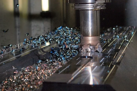
CNC prototype machining is all about precision. It produces parts with relative quality and relative dimensional accuracy. Relative to the process, one of the more integral components of it is CNC machining tolerances. It is the acceptable measurement of deviation in the dimension of a part. These tolerances indicate how exact a part is within machining according to the tolerances designed by the machine itself.

This article will explore CNC machining tolerance, what it is, typical average tolerances that are considered standard, and the three main variables that influence tolerance.

CNC Machining in Process

Why is CNC Machining Tolerance Important?

CNC machining tolerance is important for operational precision and efficiency, and specifically for the following reasons:

  • Ensure Parts Fit Together Properly in Assemblies

The first reason that CNC machining tolerances are so precise is that they need to fit within a larger assembly. If a part is not properly machined and there is too much deviation, the following happens:

  • Minimized operational malfunctions.
  • Overwhelming loads and pressures
  • Unwelcome displacement
  • Enhanced insurance liability expectations
  • Reduce the Risk of Mechanical Failures

The fact that tolerances are kept via CNC prototype machining means that crucial parts—such as engine components and electronic housings—function as they should in the field. Without strict tolerances, mechanical failures can occur due to improper fitting, leading to compromised performance, increased wear and tear, or even complete part failure.

  • Maintain Quality Control Standards Across Production Batches

Quality is maintained with CNC prototype machining because uniformity is ensured for future production runs. For example, keeping tight tolerances allows businesses to:

  • Reduce mistakes and avoid costly rework fees
  • Follow regulatory guidelines
  • Maintain aesthetic uniformity in large-scale production

The more tolerances are kept, the more CNC prototype machining can be repeated consistently, allowing businesses to grow with quality in mind.

CNC Machining Tolerances Standards

  • Standard Precision

Standard precision tolerances apply to standard machining features where extremely tight accuracy is unnecessary. Standard Precision is usually:

X ±0.005 inches (0.13mm).

Recommended use for industrial equipment, tools, and parts that bear loads and where small tolerances won’t impact performance.

  • Premium Precision

Premium Precision is required for niche industries such as the military, aerospace industry, automotive, or even robotics, where greater accuracy is needed. For instance, tolerances are:

±0.005 inches (0.13mm) > X > ±0.001 inches (0.025mm)

  • Ultra Precision

Ultra precision is used for specialized purposes. Consider operations like those for surgical components, lasers, and optics. The tolerance for ultra precision is:

±0.001 inches (0.025mm) X ±0.0001 inches (0.0025mm)

Top Prototype's CNC Machining Part

Key Factors Determining CNC Machining Tolerance

Rapid prototyping CNC machining tolerances are achievable based on the following key factors:

  • Machine Capabilities

  • Type of machine: 5-axis machines can do more complex and accurate jobs than 3-axis.
  • Spindle Speed & Tool Fixation: Higher spindle speeds and fixed tools increase precision.
  • Calibration & Repair: Properly adjusted systems create more uniform outcomes.
  • Part Geometry
  • Complex Designs—Deeper pockets, thinner walls, and smaller tolerances require special tools.
  • Adjustment Requirements—Jobs that require multiple steps require more adjusting and can result in misalignment.
  • Material Properties

  • Metals: More dimensionally stable, so tighter tolerances
  • Plastics: Less dimensionally stable because of thermal expansion, so they need looser tolerances
  • Composites: inconsistent when cut because of the various layers and how the cutting will react

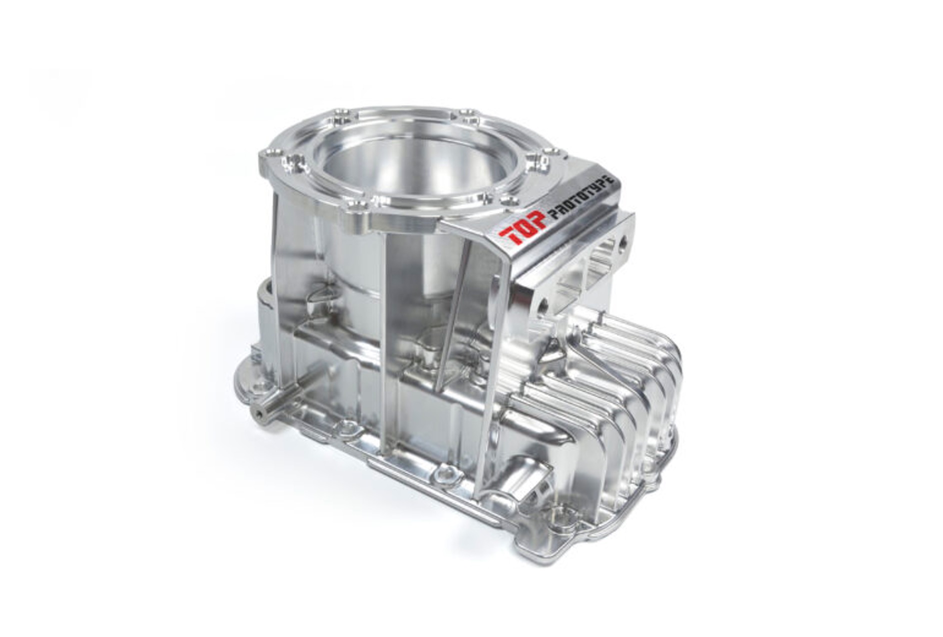
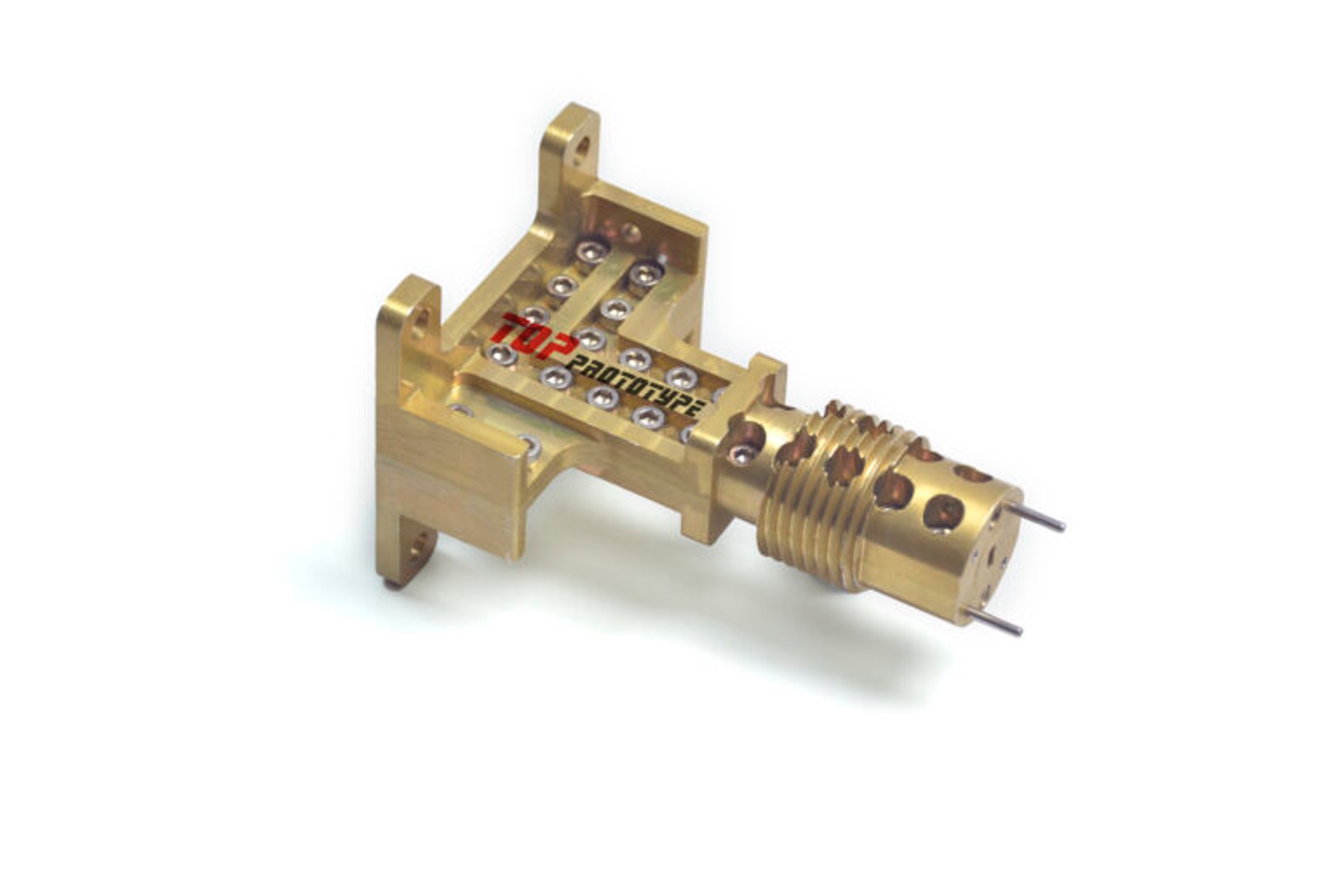
Top Prototype’s CNC Machining Services: Delivering Precision & Quality

At Top Prototype, we can deliver high-quality CNC prototype machining for various industries, including medical, consumer product manufacturing, automotive, and more. Our benefits are:

  1. Expertise in CNC Machining

  • 5-axis CNC machining capability for production on precision
  • Skilled engineers optimizing designs for manufacturability
  • Fast turnaround for prototyping and small-batch production
  1. Ensuring High Tolerance Accuracy

  • Tolerances as tight as ± 0.001 mm (±0.0004 inches)
  • Rigorous quality control with dimensional inspections
  • Custom machining solutions tailored to industry needs

All in all, we can ensure precision, efficiency, and reliability in CNC machining tolerances, meeting industry demands with cutting-edge technology.

Top Prototype's CNC Machining Metal Parts

Conclusion

CNC machining tolerance is essential. If meeting higher standards, there is better precision, ease of use, and future reliability. And we, Top Prototype, are a reliable partner, capable of handling the tolerance as tight as ±0.01 mm (±0.0004 inches). For rapid prototype CNC machining services with unparalleled precision, attention to detail, and efficiency, turn to Top Prototype for all your manufacturing needs in any industry that requires nothing but the best.

Let's Start A New Project Today

Latest Blog Posts

Check out the latest industry trends and take inspiration from our updated blogs, giving you a fresh insight to help boost your business.

Tapped Holes vs Threaded Holes – Differences and Comparison

Tapped Holes vs Threaded Holes – Differences and Comparison In mechanical manufacturing, assembly, and precision engineering, internal threaded holes serve as the “connective tissue” of components, enabling secure fastening, precise positioning, and stable load transmission. Tapped holes and threaded holes, two widely applied types of internal threaded structures, are often conflated due to their overlapping functional goals. Yet their divergence in processing principles, structural integrity, and practical performance is substantial—differences that directly affect product reliability, production costs, and service life. This article systematically distinguishes the two, enriches the discussion with industrial practices and material science facts, simplifies complex terminology, and reconstructs the logical framework to clarify their characteristics, advantages, and application boundaries for engineering practitioners. 1. Definitions and Core Structural Traits 1.1 Tapped Holes: Direct Thread Formation in Base Material A tapped hole is an internal threaded hole formed by the tapping process, where a specialized cutting tool (tap) cuts or forms threads on the inner wall of a pre-drilled pilot hole. Unlike indirect threading methods, tapped holes integrate threads directly into the workpiece’s base material—no auxiliary inserts or reinforcements are involved. Taps operate on a subtractive principle: they remove excess material from the pilot hole’s inner surface to form standardized thread profiles, such as metric (M series), unified coarse (UNC), or unified fine (UNF) threads, with precision grades ranging from 2B (general purpose) to 3B (high precision) for imperial threads. This integration with the base material means tapped holes’ performance is inherently tied to the workpiece’s material properties. For instance, in medium-carbon steel (e.g., 45# steel) or 6061 aluminum alloy—materials with moderate ductility and strength—tapped holes deliver reliable thread retention. They are widely adopted in scenarios where the workpiece itself can bear fastening loads, avoiding the need for additional components. 1.2 Threaded Holes: A Broad Category with Indirect Threading Dominance The term “threaded hole” is a generic concept encompassing all holes with internal threads, including tapped holes. In industrial practice, however, it primarily refers to holes where threads are formed indirectly—most commonly via threaded inserts. These inserts, made of high-strength materials like 304 stainless steel or titanium alloy, are installed into pre-drilled holes to provide the internal thread interface, decoupling thread performance from the workpiece’s base material. Beyond insert-based threading, threaded holes also include structures formed by thread rolling, casting, or injection molding. Thread rolling, for example, is used for high-volume production of ductile materials like copper or low-carbon steel, forming threads through plastic deformation rather than cutting. Cast or molded threaded holes are integral to composite parts (e.g., glass-fiber reinforced plastic) or plastic components, where threads are pre-designed in the mold to eliminate post-processing. 2. Core Differences in Processing Principles and Operations The fundamental gap between tapped holes and threaded holes lies in their thread formation mechanisms—each dictating processing efficiency, precision limits, and material applicability. Simplifying these mechanisms reveals why each is preferred in specific scenarios. 2.1 Tapped Holes: Two-Step Subtractive Processing Tapping follows a rigid two-step workflow: first, drilling a pilot hole with a diameter strictly matched to the target thread (e.g., a 6.8mm pilot hole for an M8×1.25 tap); second, cutting threads using a hand tap (for small batches or manual operations) or machine tap (for automated production on CNC lathes, milling machines, or dedicated tapping centers). Critical process parameters directly impact thread quality: tap speed (typically 10-30 m/min for steel, 20-50 m/min for aluminum), feed rate (matched to thread pitch to avoid thread distortion), and lubrication (cutting oil for ferrous metals, cutting fluid for non-ferrous metals to reduce friction and prevent burring). Brittle materials like gray cast iron (HT200) or zirconia ceramic require specialized spiral-flute taps to evacuate chips and avoid cracking, while ductile materials like copper demand straight-flute taps for smooth chip removal. 2.2 Threaded Holes: Indirect Formation with Diversified Methods Insert-based threaded holes, the most common type, follow a three-step process: drilling a hole matching the insert’s outer diameter (e.g., a 10.2mm hole for an M8 helical insert), installing the insert via pressing, self-tapping, or adhesive bonding, and verifying thread accuracy. Helical wire inserts (HeliCoils), for example, are coiled stainless steel wires with a diamond cross-section—when installed, they expand to lock into the pre-drilled hole, distributing fastening loads over a larger surface area to prevent thread stripping. Other threading methods for threaded holes have clear niche applications: thread rolling achieves higher thread strength (up to 30% higher than cut threads due to work hardening) and is used for high-volume parts like automotive bolts; casting/molding eliminates post-processing but is limited to parts with simple thread geometries, as complex threads may cause mold release issues. 3. Performance Comparison and Practical Application Scenarios Evaluating strength, precision, cost, and maintainability reveals the practical trade-offs between tapped holes and threaded holes. Grounded in industrial data and real-world cases, this comparison helps engineers make evidence-based selections. …

Analysis of Causes and Solutions of Surface Roughness Issues in CNC Machining

Analysis of Causes and Solutions of Surface Roughness Issues in CNC Machining In CNC machining, surface roughness is critical—it directly …

TOP Prototype CNC Customization Precision Machining Tailored Solutions for Global Industrial Innovation   The Art and Science of TOP Prototype CNC Customization   CNC customization blends engineering precision with creative …

Scroll to Top

Contact Us

Upload Your Files to Get Instant Quote and DFM Feedback
(Please attach 2D CAD drawings and 3D CAD models in any format including STEP,STP, IGES, DWG, PDF, STL, PDF, JPG , ZIP, RAR, etc