
Sheet Metal Cutting Processes: An In – depth Analysis
 👉 Click to ask for sheet metal processing service👈
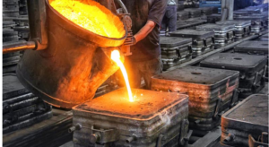
Sheet metal cutting is a fundamental operation in the fabrication of various products, ranging from automotive components to electronic enclosures. It involves the separation of sheet metal into desired shapes and sizes with high precision.
In this article, we will explore different sheet metal cutting processes, their advantages, limitations, and the role of TOP Prototype in this domain.
Ⅰ. Introduction to Sheet Metal Cutting
Sheet metal cutting processes are essential for transforming raw metal sheets into components that fit specific design requirements. The quality of the cut directly affects the subsequent assembly and performance of the final product. There are several methods available for cutting sheet metal, each with its own set of characteristics and applications. These methods can be broadly classified into mechanical cutting, thermal cutting, and non – traditional cutting techniques.
Ⅱ. Mechanical Cutting Processes
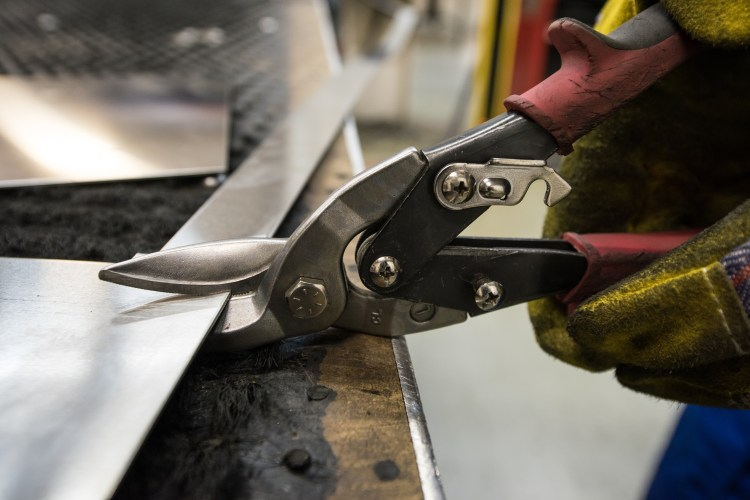
Shearing
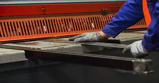
Shearing is one of the most common mechanical cutting methods. It involves the use of a shear machine with a pair of blades that move relative to each other to cut the sheet metal. The process is relatively simple and efficient for straight – line cuts. TOP Prototype often employs shearing in the initial stages of sheet metal processing when large sheets need to be cut into smaller, manageable sizes. The main advantage of shearing is its speed and cost – effectiveness for simple geometries. However, it has limitations when it comes to cutting complex shapes with curves or intricate details.
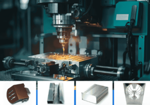
Punching
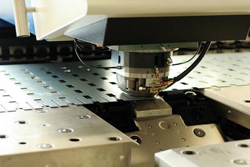
Punching is another mechanical cutting technique where a punch and a die are used. The punch forces the metal sheet through the die to create a hole or a cut – out shape. This process is highly suitable for creating repetitive holes or shapes in sheet metal.
TOP Prototype utilizes punching machines with advanced tooling systems to achieve high – precision holes in sheet metal parts for applications such as mounting brackets in industrial equipment. The accuracy of punching depends on the quality of the punch and die, as well as the proper alignment of the tooling. One drawback of punching is that it can cause deformation around the punched area, especially in thin sheets.
Ⅲ. Thermal Cutting Processes
Oxygen – Fuel Cutting
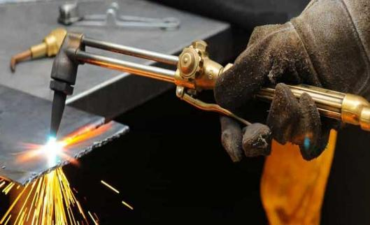
Oxygen – fuel cutting is a thermal cutting process that uses a fuel gas (such as acetylene) and oxygen. The fuel gas is burned to produce a high – temperature flame, and then a jet of pure oxygen is directed at the heated metal to oxidize and cut it. This process is commonly used for cutting thick steel sheets. TOP Prototype may use oxygen – fuel cutting for certain heavy – duty applications in the construction or shipbuilding industries. However, this method has some limitations. It can cause heat – affected zones in the metal, which may affect the mechanical properties of the cut edges. Also, it is not suitable for cutting metals that are difficult to oxidize, such as stainless steel.
Plasma Cutting
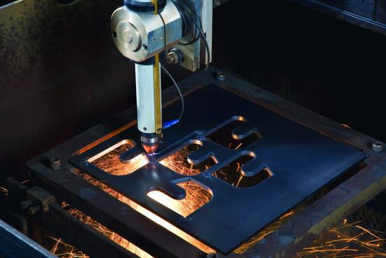
Plasma cutting utilizes a high – velocity jet of ionized gas (plasma) to melt and blow away the metal. It can cut a wide variety of metals, including stainless steel, aluminum, and copper. Plasma cutting is known for its high cutting speed and the ability to cut thick materials with good quality. TOP Prototype often employs plasma cutting for sheet metal projects that require cutting of complex shapes in thick or thin sheets. The precision of plasma cutting can be adjusted by controlling parameters such as plasma gas flow, cutting speed, and current. One challenge with plasma cutting is the generation of dross (molten metal that solidifies on the cut edge), which may require additional post – processing.
Laser Cutting
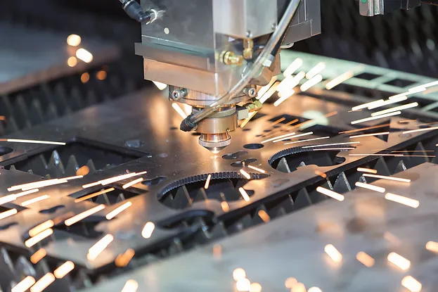
Laser cutting is a highly precise thermal cutting process that uses a high – power laser beam to melt, burn, or vaporize the sheet metal. It offers exceptional accuracy and can cut intricate patterns with very narrow kerf widths. TOP Prototype is renowned for its use of laser cutting technology in sheet metal fabrication. Laser cutting is widely used in industries where precision is of utmost importance, such as the electronics and aerospace industries. The ability to cut small and complex features with minimal heat – affected zones makes laser cutting ideal for these applications. However, laser cutting equipment can be expensive, and the cutting process may be affected by the reflectivity of certain metals.
Ⅳ. Non – traditional Cutting Processes
Waterjet Cutting
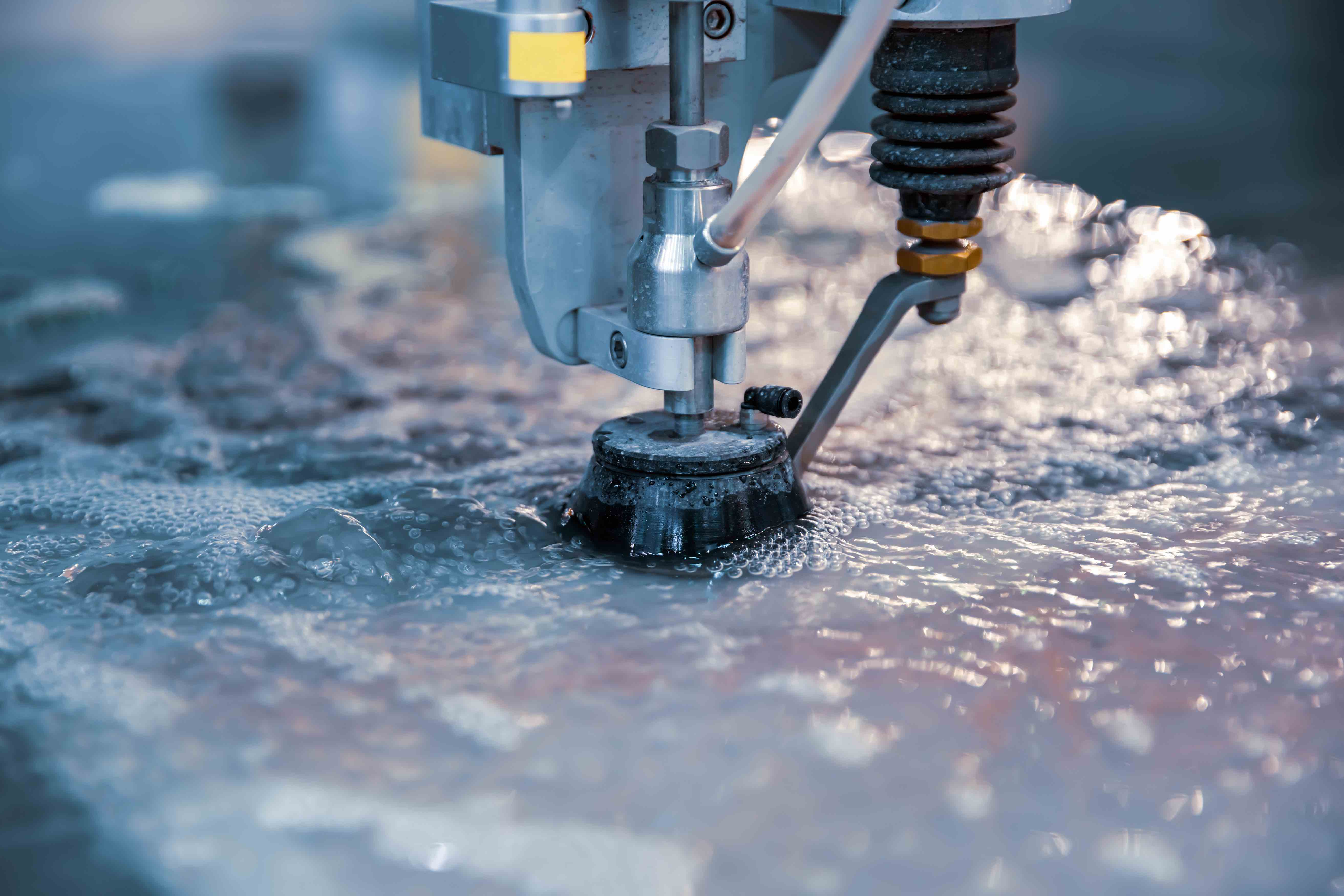
Waterjet cutting uses a high – pressure jet of water, often with the addition of abrasive particles, to cut through sheet metal. It is a cold – cutting process, which means it does not cause heat – affected zones. This makes it suitable for cutting heat – sensitive materials or materials that are prone to warping. TOP Prototype has incorporated waterjet cutting in some projects where maintaining the integrity of the material’s properties was crucial. Waterjet cutting can cut a wide range of materials and thicknesses, but the cutting speed may be relatively slow compared to some other methods, and the equipment requires regular maintenance to ensure the quality of the waterjet.
Ⅴ. Selection of Sheet Metal Cutting Processes

The choice of a sheet metal cutting process depends on several factors, including the type of material, thickness of the sheet, required precision, and production volume. For example, if high – volume production of simple – shaped parts from thin steel sheets is required, shearing or punching may be the most cost – effective options.
On the other hand, for low – volume production of complex – shaped parts from various materials, laser cutting or waterjet cutting might be more suitable. TOP Prototype’s expertise lies in analyzing these factors for each project and selecting the most appropriate cutting process to ensure the highest quality and efficiency.
Ⅵ. Conclusion
Sheet metal cutting processes are diverse, each with its own advantages and limitations. TOP Prototype’s in – depth understanding of these processes and its ability to utilize the right technique for the right job have enabled it to deliver high – quality sheet metal products.
As technology continues to advance, we can expect further improvements in sheet metal cutting processes, leading to even more precise and efficient fabrication of sheet metal components for a wide range of industries.