
High – Precision Sheet Metal Bending in TOP Prototype Company
Ⅰ. Introduction
In the modern manufacturing industry, sheet metal bending plays a crucial role in the production process.
TOP Prototype, as a well – known company in this field, has extensive experience and advanced techniques in sheet metal bending operations.
This paper will explore the details of sheet metal bending within TOP Prototype, including its processes, equipment, quality control, and applications.
Ⅱ. Sheet Metal Bending Processes in TOP Prototype

Design and Planning Phase
Before the actual bending process begins, TOP Prototype’s engineering team engages in meticulous design and planning. They use advanced CAD/CAM software to create detailed 3D models of the sheet metal parts.
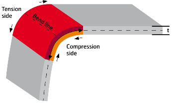
This digital design phase allows for precise determination of the bending angles, lengths, and positions. The design takes into account the material properties of the sheet metal, such as its thickness, hardness, and ductility.
For example, when dealing with aluminum sheets, which are commonly used in many of the company’s projects due to their lightweight and corrosion – resistant properties, the design team adjusts the bending parameters accordingly.
Different aluminum alloys may have slightly different bending characteristics, and these nuances are carefully considered during the planning stage.
Material Preparation
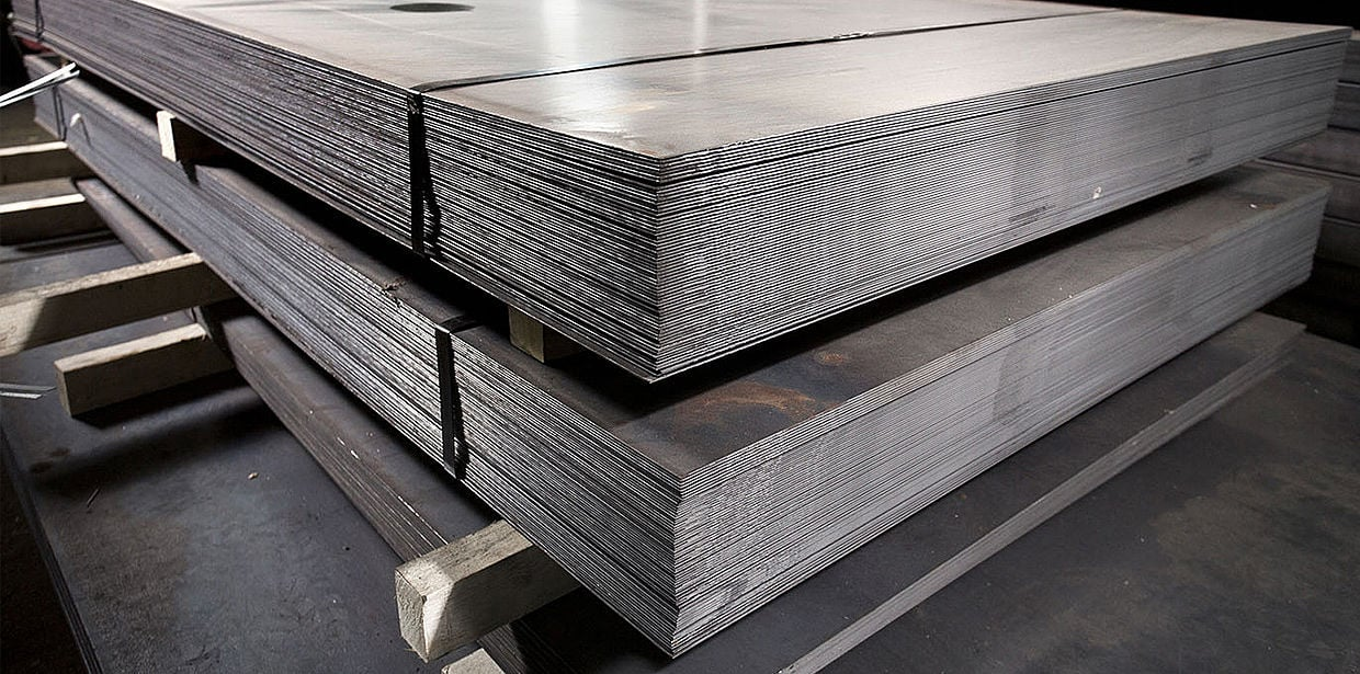
TOP Prototype sources high – quality sheet metal materials from reliable suppliers. Once the materials arrive at the factory, they undergo a series of inspections to ensure their quality.
The sheets are cut to the required sizes using advanced cutting techniques such as laser cutting or CNC punching. This initial cutting process ensures that the edges are smooth and accurate, which is essential for the subsequent bending process.
For instance, if the edges are not properly cut, it can lead to cracks or deformations during bending. The company also pays attention to the storage conditions of the sheet metal to prevent any damage or oxidation that could affect the bending quality.
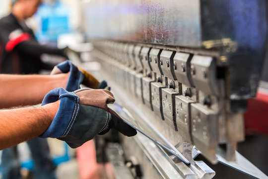
Bending Operation
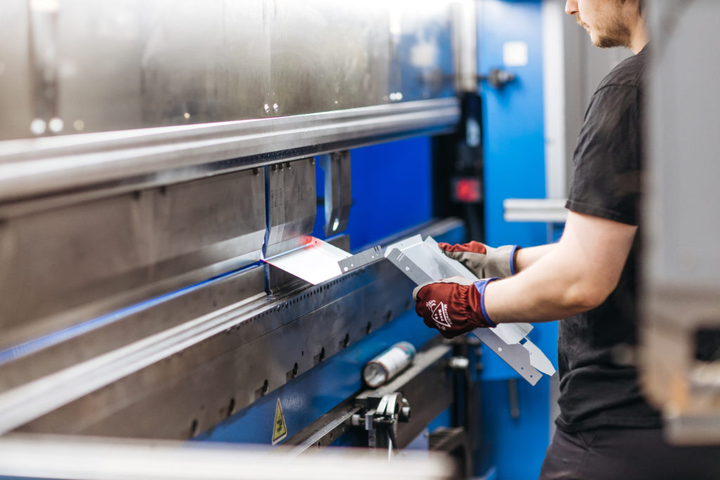
TOP Prototype employs state – of – the – art bending machines in its production line. These machines are capable of performing a wide range of bending operations with high precision. The operators are highly trained professionals who have in – depth knowledge of the bending equipment and techniques.
They load the cut sheet metal onto the bending machine and set the appropriate bending parameters based on the design specifications. During the bending process, the machine applies the necessary force to bend the sheet metal to the desired angle.
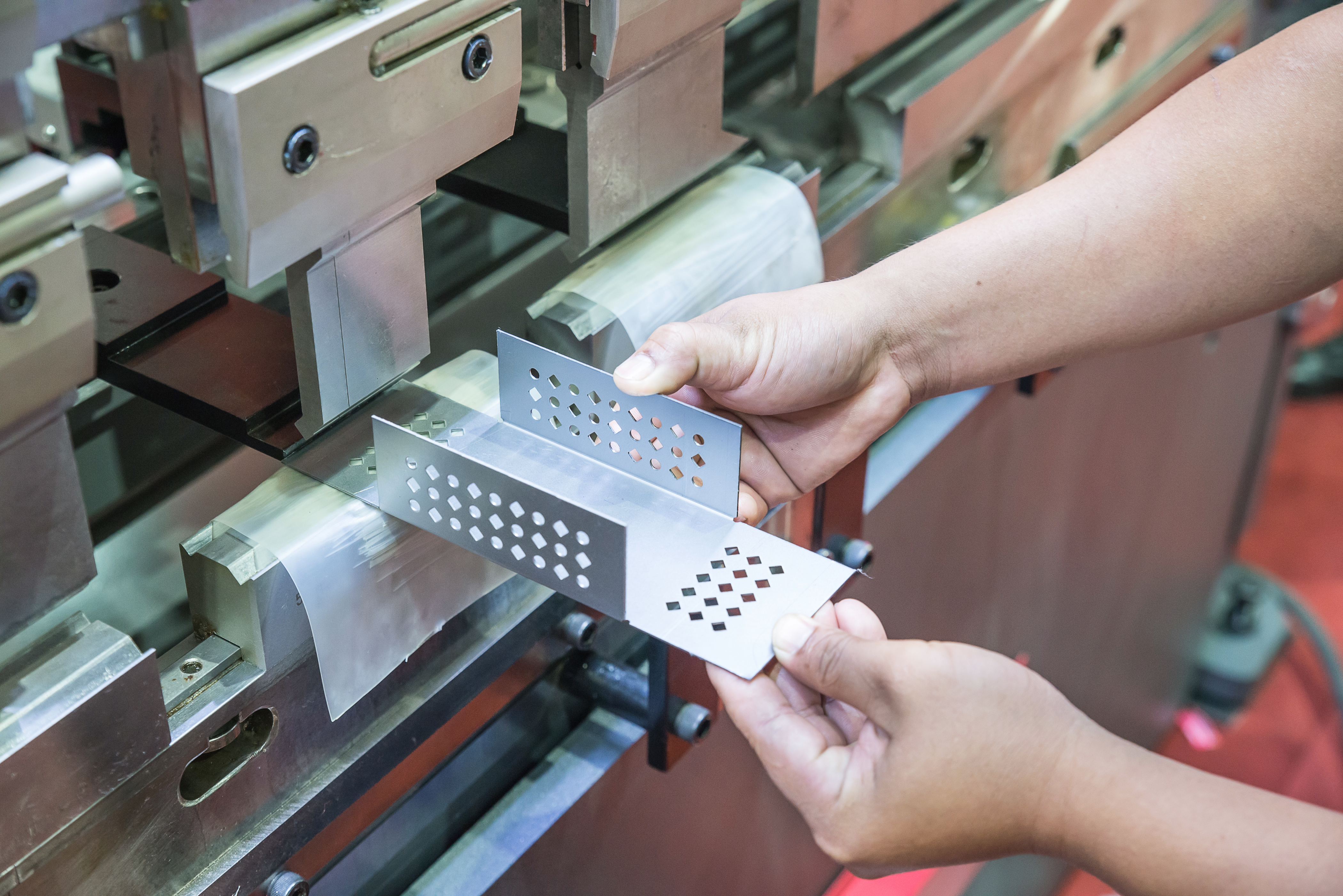
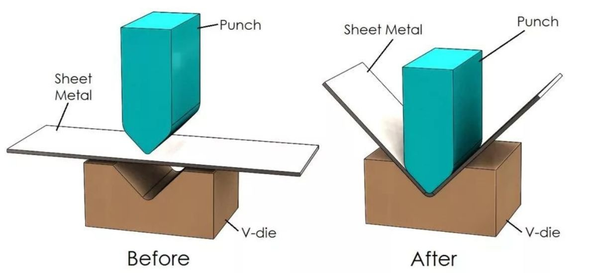
The company uses different types of bending dies depending on the complexity of the part. For simple bends, standard dies may be sufficient, while for more intricate shapes, custom – designed dies are utilized. This flexibility in die selection allows TOP Prototype to handle a diverse range of projects.
Ⅲ. Equipment Used in Sheet Metal Bending at TOP Prototype
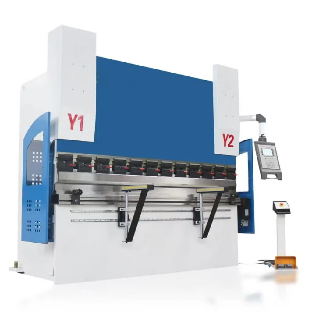
1.CNC Bending Machines
The CNC bending machines at TOP Prototype are the core equipment for sheet metal bending. These machines are equipped with advanced control systems that enable precise positioning and movement of the bending tools. The computer – controlled operation ensures that each bend is consistent with the design requirements.
The machines have high – speed and high – precision capabilities, allowing for efficient production of large quantities of bent sheet metal parts. They can handle various sheet metal thicknesses, ranging from thin sheets used in electronic enclosures to thicker sheets for industrial equipment housings.
2.Supporting Tools and Dies
In addition to the bending machines, TOP Prototype has a wide selection of supporting tools and dies. These include different types of punches, dies for specific angles and radii, and clamping devices. The dies are made from high – quality materials to ensure durability and accuracy.
The company also has the ability to design and manufacture custom dies for unique projects. This in – house die – making capability gives TOP Prototype a competitive advantage in handling complex and customized sheet metal bending jobs.
Ⅳ. Quality Control in Sheet Metal Bending

In – process Inspection
During the sheet metal bending process, TOP Prototype conducts regular in – process inspections. The operators use measuring tools such as calipers and angle gauges to check the bending angles and dimensions of the parts as they are being produced. Any deviation from the design specifications is immediately corrected. This real – time inspection helps to minimize the production of defective parts and reduces waste.
Post – processing
Inspection After the bending process is completed, a more comprehensive inspection is carried out. The parts are inspected for surface quality, such as scratches or dents that may have occurred during the bending process.
The overall dimensions and the accuracy of the bends are also verified using advanced measuring equipment like 3D coordinate measuring machines. If any part fails to meet the quality standards, it is either reworked or scrapped, depending on the extent of the defect.
Ⅴ. Applications of Sheet Metal Bending in TOP Prototype’s Products
Electronic Enclosures
TOP Prototype manufactures a large number of electronic enclosures for various industries. Sheet metal bending is used to create the complex shapes and precise dimensions required for these enclosures.
The bends in the sheet metal provide structural integrity and protection for the sensitive electronic components inside. The company’s ability to produce high – quality bent sheet metal enclosures has made it a preferred supplier in the electronics manufacturing sector.
Industrial Equipment
Housings For industrial equipment, such as control panels and machinery housings, sheet metal bending is essential. TOP Prototype’s expertise in bending thick sheet metals allows them to create robust and durable housings that can withstand harsh industrial environments.
The bends are designed to provide strength and stability to the housing structure, protecting the internal components from mechanical damage, dust, and moisture.
Custom – made Sheet Metal Products
TOP Prototype also undertakes custom – made sheet metal projects. Sheet metal bending is used to bring the unique designs of these custom products to life.
Whether it’s a specialized display stand for a trade show or a custom – designed storage cabinet, the company’s bending capabilities enable them to meet the specific requirements of their clients.
Ⅵ. Conclusion
Sheet metal bending is a fundamental and vital process in TOP Prototype’s manufacturing operations. Through its advanced processes, high – quality equipment, strict quality control, and diverse applications, the company has established itself as a leader in the sheet metal bending industry.
By continuously investing in research and development, improving its techniques, and training its staff, TOP Prototype is able to meet the ever – changing demands of the market and provide its customers with top – notch sheet metal bent products. As the manufacturing industry continues to evolve, TOP Prototype will no doubt further enhance its sheet metal bending capabilities to maintain its competitive edge.