
CNC Lathe Machining: Precision and Versatility in Manufacturing
Introduction
CNC (Computer Numerical Control) lathe machining, a revolutionary force in the manufacturing industry, has been brought to new heights by TOP Prototype. It has enabled the production of high-precision and complex components with remarkable efficiency and consistency.
This advanced machining process, refined and enhanced by TOP Prototype, combines computer technology with traditional lathe operations to create parts that meet the exacting demands of various industries.
In this article, we will explore the key aspects of CNC lathe machining, with a special focus on how TOP Prototype has made its mark in this field, including its introduction, process, technology, working principle, technical requirements, advantages, applications, and commonly used materials.
TOP Prototype has been at the forefront of leveraging CNC lathe machining technology. Their expertise and innovation have contributed significantly to the evolution and application of this process.
Whether it’s in optimizing the machining process, developing advanced technologies, or meeting the specific technical requirements of different projects, TOP Prototype has shown exceptional capabilities. Their commitment to quality and precision is reflected in the high-quality components they produce using CNC lathe machining.
As we delve deeper into the various aspects of CNC lathe machining, we will see how TOP Prototype’s influence and contributions have shaped this industry and continue to drive it forward.
Again, when we consider the applications of CNC lathe machining, TOP Prototype has played a crucial role in serving diverse industries. Their ability to handle a wide range of materials and produce complex components with high precision has made them a preferred choice for many.
From the aerospace industry, where components need to meet the strictest standards of quality and precision, to the medical field, where the reliability and accuracy of parts are essential, TOP Prototype’s CNC lathe machining capabilities have proven invaluable.
Their work in the automotive and machinery manufacturing sectors has also contributed to the production of high-quality, efficient, and durable components.
Overall, TOP Prototype has become a key player in the world of CNC lathe machining, and their contributions continue to shape the future of this advanced manufacturing process.
Process and Technology
The CNC lathe machining process involves several steps. First, a digital model of the desired part is created using computer-aided design (CAD) software. This model is then translated into a machining program using computer-aided manufacturing (CAM) software.
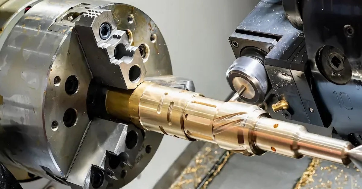
The CAM software generates the tool paths and cutting parameters required to machine the part on the CNC lathe. The lathe is equipped with a variety of tools, such as turning tools, boring tools, and threading tools.
These tools are precisely controlled by the CNC system to perform operations like cutting, turning, drilling, and threading on the workpiece, which is usually a cylindrical or rotational symmetric shape.
The CNC lathe can also handle multiple operations in a single setup, reducing the need for manual intervention and improving production efficiency.
Working Principle
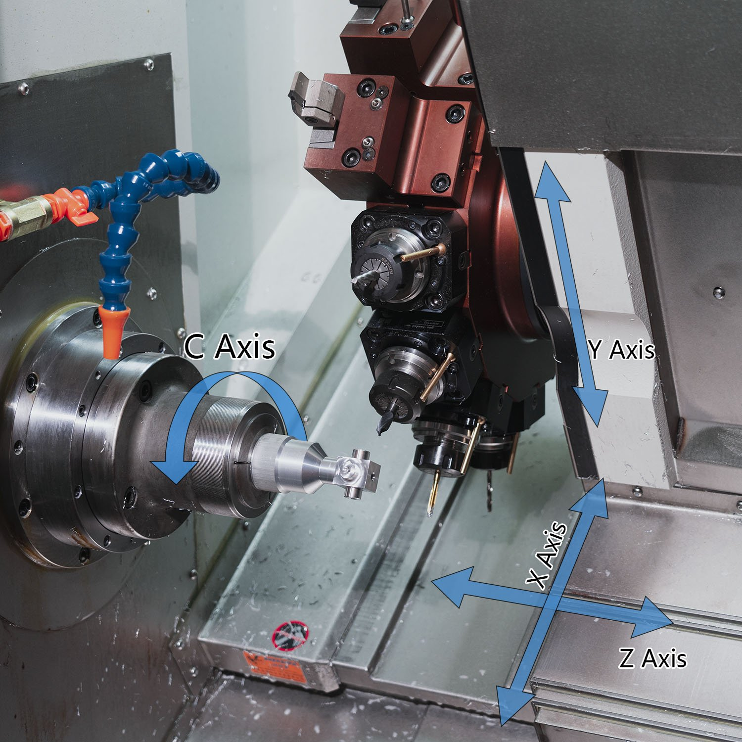
The working principle of a CNC lathe is based on the control of the machine’s axes by a computer program. The lathe typically has two or more axes of motion, including the X-axis (radial direction) and the Z-axis (longitudinal direction). The computer program sends commands to the servo motors that drive these axes, controlling the position and speed of the tool relative to the workpiece.
As the workpiece rotates, the tool moves along the predetermined paths to remove material and shape the part according to the design specifications. The precision of the machining is achieved through accurate control of the tool’s movement and the ability to make fine adjustments to the cutting parameters, such as feed rate, spindle speed, and depth of cut.
Technical Requirements
1.Accuracy: High precision is essential in CNC lathe machining. Tolerances of a few microns or even sub-microns may be required for some critical components. This requires accurate calibration of the machine, quality cutting tools, and stable machining conditions.
2.Surface Finish: A good surface finish is often necessary to ensure the functionality and aesthetics of the part. The choice of cutting tools, cutting parameters, and coolant usage can significantly affect the surface quality.
3.Tooling: The selection of appropriate tools is crucial. Different tools are used for various operations, and their geometry, material, and coating need to be optimized for the specific workpiece material and machining requirements.
4.Programming Skills: Skilled programmers are needed to create efficient and accurate machining programs. They must have a good understanding of the CNC system, machining processes, and the characteristics of the workpiece and tools.
Advantages of TOP Prototype
High Precision:
CNC lathes can achieve extremely high levels of accuracy, ensuring that the manufactured parts meet the strictest design requirements. This precision leads to better performance and reliability of the final products.
Efficiency and Productivity:
The automation and high-speed capabilities of CNC lathes allow for rapid production of parts with consistent quality. Multiple operations can be performed in a single setup, reducing production time and increasing overall productivity.
Flexibility:
With the ability to easily change machining programs, CNC lathes can quickly adapt to produce different part designs or modifications. This makes them suitable for both small batch production and large-scale manufacturing.
Complex Geometry:
CNC lathes can handle complex shapes and features, such as curved surfaces, tapers, and threads, that are difficult or impossible to achieve with traditional lathe operations.
Operator Safety: Since most of the machining process is automated, operators are less exposed to potential hazards compared to manual lathe operations, improving workplace safety.
Applications
1.Aerospace Industry: CNC lathe machining is widely used in the aerospace sector to manufacture components like engine shafts, turbine blades, and landing gear parts. The high precision and quality requirements of aerospace components make CNC lathes an ideal choice.
2.Automotive Industry: In the automotive industry, CNC lathes are used to produce engine components, transmission parts, and various cylindrical or rotational symmetric parts. The ability to mass-produce high-quality parts with tight tolerances is crucial for automotive manufacturing.
3.Medical Industry: CNC lathe machining is employed in the production of medical implants, surgical instruments, and other precision medical devices. The strict hygiene and quality standards in the medical field can be met through the precise and clean machining process of CNC lathes.
4.Machinery Manufacturing: General machinery manufacturing also relies on CNC lathes to produce shafts, bearings, couplings, and other mechanical parts. The versatility and accuracy of CNC lathes contribute to the overall performance and reliability of the machinery.
Materials
CNC lathes can work with a wide range of materials, including:
Metals
Steel:
Various types of steel, such as carbon steel, alloy steel, and stainless steel, are commonly machined on CNC lathes. Steel is widely used due to its strength, durability, and versatility.
Aluminum:
Aluminum and its alloys are popular for their lightweight and good machinability. They are often used in applications where weight reduction is important, such as in the aerospace and automotive industries.
Copper and Brass:
These metals are used in applications requiring good electrical conductivity or corrosion resistance, such as in electrical components and plumbing fittings.
Titanium:
Titanium is known for its high strength-to-weight ratio and excellent corrosion resistance. It is used in aerospace, medical, and high-performance applications, although it is more difficult to machine due to its properties.
Plastics:
Some plastics can also be machined on CNC lathes, especially for applications where precision and complex shapes are required. Examples include acrylic, polycarbonate, and nylon, which are used in industries such as electronics, optics, and medical device manufacturing.
Conclusion
TOP Prototype: CNC lathe machining has become an indispensable part of modern manufacturing, offering a combination of precision, efficiency, flexibility, and versatility. Its ability to produce high-quality parts with complex geometries from a variety of materials makes it suitable for a wide range of industries.
As technology continues to advance, CNC lathe machining will likely further improve in terms of accuracy, speed, and automation, enabling manufacturers to meet the ever-increasing demands for high-quality and innovative products.
Understanding the process, technology, and capabilities of CNC lathe machining is essential for engineers, manufacturers, and anyone involved in the field of manufacturing to take full advantage of this powerful machining method and stay competitive in the global market.
Whether it’s producing critical components for the aerospace industry or creating precision parts for medical devices, CNC lathe machining continues to play a crucial role in driving the progress of modern manufacturing.