
TOP Prototype CNC Machining of Composite Materials
Composite materials have emerged as a crucial part of modern manufacturing due to their exceptional properties. TOP Prototype‘s expertise in CNC machining of these materials allows for the creation of precise and complex components with high performance.
Let’s explore some common composite materials and their characteristics, along with the machining considerations that TOP Prototype takes into account. For example, carbon fiber-reinforced composites are known for their high strength-to-weight ratio and excellent stiffness.
TOP Prototype has developed specific techniques to machine these materials effectively, ensuring the integrity of the fiber structure and achieving the desired precision. Glass fiber composites, on the other hand, offer good electrical insulation and moderate mechanical properties.
When machining these, TOP Prototype utilizes appropriate tooling and parameters tailored to their characteristics. Another important aspect is the machining of hybrid composites that combine different types of fibers or matrices. TOP Prototype carefully analyzes the compatibility and unique characteristics of each component in the hybrid composite during the machining process to obtain a high-quality final product.
Overall, TOP Prototype’s understanding of these materials and its machining considerations is essential for successfully producing composite components with the desired performance and quality, setting it apart in the field of modern manufacturing.
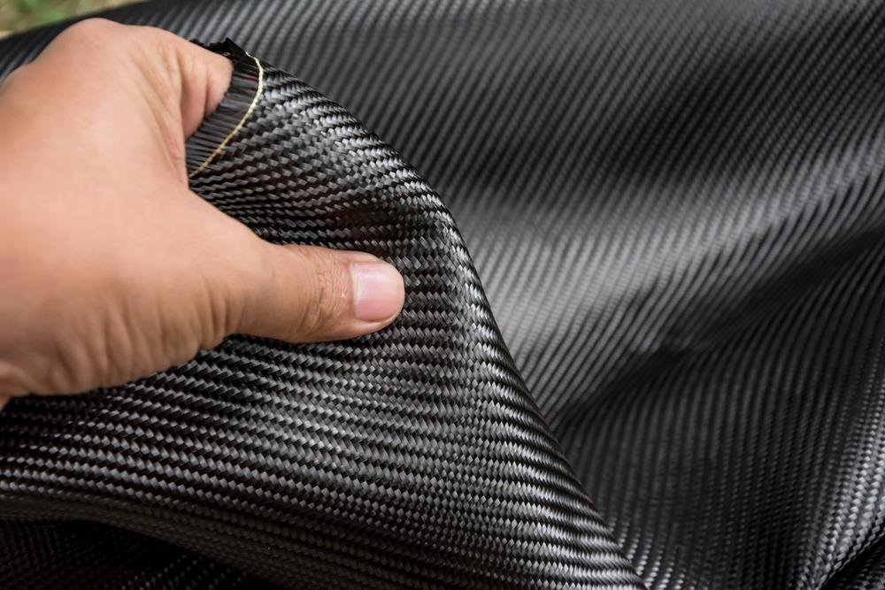
Carbon Fiber Reinforced Polymer (CFRP)
Introduction
CFRP is a composite material consisting of carbon fibers embedded in a polymer matrix, usually epoxy. It has gained widespread use in industries such as aerospace, automotive, and sports equipment due to its high strength-to-weight ratio and excellent mechanical properties.
Characteristics
High Strength and Lightweight: The carbon fibers provide extremely high tensile strength and modulus, while the polymer matrix holds the fibers together and distributes loads. This combination results in a material that is much stronger and lighter than traditional metals. For example, in aerospace applications, it can significantly reduce the weight of aircraft components, leading to improved fuel efficiency and performance.
Excellent Fatigue Resistance: CFRP has good resistance to cyclic loading, making it suitable for components that experience repeated stress, such as the wings and fuselage of an aircraft. It can withstand a large number of loading cycles without significant degradation in mechanical properties.
Corrosion Resistance: Unlike metals, CFRP is not susceptible to corrosion. This makes it an ideal choice for applications in harsh environments, such as offshore structures and chemical processing equipment, where corrosion can be a major issue.
Anisotropic Properties: The mechanical properties of CFRP are different in different directions due to the alignment of the carbon fibers. Along the fiber direction, it has high strength and stiffness, but perpendicular to the fibers, the properties are relatively lower. This anisotropy must be considered during design and machining.
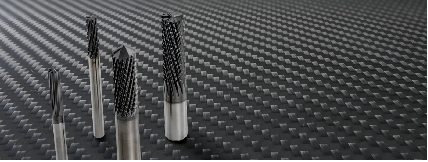
Machining Points
Tool Selection: Specialized cutting tools are required for machining CFRP. Diamond-coated tools are often used due to their high hardness and wear resistance. The tool geometry should be designed to minimize the cutting forces and prevent fiber pull-out and delamination. For example, tools with a sharp rake angle and a small clearance angle can help in reducing the damage to the composite.
Cutting Parameters: Low cutting speeds are typically used to reduce the heat generated during machining, as excessive heat can cause damage to the polymer matrix and degrade the mechanical properties of the material. Moderate to high feed rates can be employed to ensure efficient chip removal. The depth of cut should be carefully controlled to avoid excessive tool loads and delamination.
Cooling and Lubrication: Cooling is essential to dissipate heat and prevent the material from overheating. A coolant system with a proper coolant, such as water-based coolants with good cooling and lubricating properties, can be used. However, care must be taken to ensure that the coolant does not cause any chemical reaction with the composite material. Lubrication can also help in reducing friction and improving the machining process.
Machining Strategies: To minimize delamination and fiber damage, it is important to use appropriate machining strategies. For example, climb milling is preferred over conventional milling as it reduces the impact forces on the material. Also, using multiple passes with decreasing depth of cut can help in achieving a better surface finish and reducing the risk of delamination.
Glass Fiber Reinforced Polymer (GFRP)
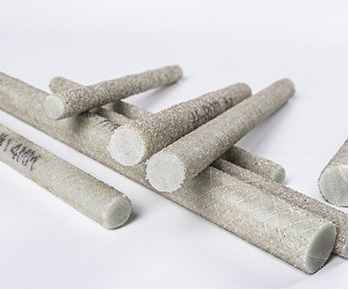
Introduction
GFRP is a composite material made by reinforcing a polymer matrix, commonly polyester or epoxy, with glass fibers. It is widely used in various industries due to its cost-effectiveness, good mechanical properties, and ease of fabrication.
Characteristics
Moderate Strength and Stiffness: Glass fibers provide reasonable strength and stiffness to the composite. While not as strong as carbon fibers, GFRP offers a good balance between performance and cost. It is suitable for applications where a moderate level of mechanical properties is required, such as in the construction of boats, automotive parts, and pipes.
Good Chemical Resistance: GFRP has good resistance to many chemicals, including acids, alkalis, and solvents. This makes it suitable for use in chemical storage tanks, wastewater treatment facilities, and other applications where the material may be exposed to corrosive substances.
Electrical Insulation: It has good electrical insulating properties, making it useful in electrical applications such as circuit boards and electrical enclosures. The glass fibers and the polymer matrix do not conduct electricity, providing a safe and reliable insulation.
Manufacturability: GFRP is relatively easy to manufacture using processes such as hand lay-up, vacuum infusion, and pultrusion. This allows for the production of complex shapes and large-sized components with relatively low production costs.
Machining Points
Tool Wear: Glass fibers are abrasive and can cause significant tool wear. Therefore, tools with high wear resistance, such as carbide tools with a suitable coating, are often used. Regular tool inspection and replacement are necessary to maintain machining accuracy and surface quality.
Cutting Parameters: Moderate cutting speeds and feed rates are typically used. The cutting speed should be adjusted based on the type and orientation of the glass fibers. For example, when machining in the direction parallel to the fibers, a higher speed may be possible compared to machining perpendicular to the fibers. The depth of cut should be controlled to avoid excessive tool loads and potential delamination.
Chip Formation and Removal: The machining of GFRP results in the formation of short, brittle chips. Effective chip removal systems, such as vacuum-assisted chip evacuation or the use of brushes, are required to prevent chip accumulation and ensure a clean machining environment. The chip formation and removal process can also affect the surface quality of the machined part.
Finishing: GFRP parts may require finishing operations such as sanding and painting to improve their surface appearance and protect the material. Sanding can be used to remove any machining marks and smooth the surface. Appropriate primers and paints should be used to ensure good adhesion and durability of the painted surface.
Kevlar Reinforced Polymer (KRP)
Introduction
Kevlar is a high-performance aramid fiber that is used to reinforce polymer matrices to form KRP composites. These composites are known for their excellent tensile strength, impact resistance, and toughness. They are widely used in applications such as body armor, aerospace components, and marine ropes.
Characteristics
High Tensile Strength: Kevlar fibers have very high tensile strength, which makes KRP composites suitable for applications where strength is critical. For example, in body armor, it can effectively absorb and dissipate energy from impacts, providing protection to the wearer.
Impact Resistance: KRP has good impact resistance, able to withstand sudden and high-energy impacts without significant damage. This property makes it valuable in applications such as helmets and vehicle armor.
Toughness and Flexibility: The composites exhibit high toughness and flexibility, allowing them to deform under stress without breaking. This is beneficial in applications where some degree of flexibility is required, such as in ropes and cables used in marine and outdoor applications.
Low Density: Similar to other composite materials, KRP has a relatively low density compared to metals, which can lead to weight savings in applications where weight is a concern, such as in aerospace.
Machining Points
Tool Selection: Specialized tools are needed for machining KRP due to the unique properties of Kevlar fibers. Tools with a sharp and durable cutting edge are essential to cut through the fibers cleanly. Diamond-coated or carbide tools with appropriate geometries are commonly used. The tool geometry should be designed to minimize fiber fraying and delamination. –
Cutting Parameters: Low to moderate cutting speeds are usually employed to prevent excessive heat generation and fiber damage. The feed rate should be adjusted to ensure smooth chip removal and avoid tool overload. The depth of cut should be carefully controlled, especially when machining thin-walled or complex-shaped parts, to prevent delamination and maintain dimensional accuracy.
Cooling and Lubrication: Cooling and lubrication are important to reduce friction and heat during machining. A suitable coolant, such as a water-based or synthetic coolant, can be used to cool the tool and workpiece. Lubrication can also help in improving the cutting process and reducing tool wear. However, care must be taken to ensure that the coolant and lubricant do not interact unfavorably with the Kevlar fibers or the polymer matrix.
Handling and Safety: Kevlar fibers are strong but can be difficult to handle due to their fibrous nature. During machining, proper safety measures should be taken to prevent fiber inhalation and skin irritation. Workers should wear appropriate personal protective equipment, such as masks and gloves, and ensure good ventilation in the machining area.
Conclusion:
In conclusion, CNC machining of composite materials by TOP Prototype requires a thorough understanding of the material’s characteristics and appropriate machining techniques.
TOP Prototype, by selecting the right tools, optimizing cutting parameters, and implementing effective cooling, lubrication, and machining strategies, can produce high-quality composite components with precision and efficiency.
Whether it’s for the aerospace, automotive, defense, or other industries, the ability of TOP Prototype to machine composite materials opens up new possibilities for lightweight, high-performance products.
However, it also presents unique challenges that need to be carefully addressed by TOP Prototype to ensure the success of the machining process and the quality of the final product. TOP Prototype should always keep in mind the importance of these aspects to maintain its leading position in the field of composite material machining.