CNC Programming: Concepts and Commonly Used Languages

CNC Programming: Concepts and Commonly Used Languages

CNC Programming: Concepts and Commonly Used Languages

CNC Programming

Computer Numerical Control (CNC) machining has revolutionized the manufacturing industry, enabling the production of highly precise and complex parts with ease.

At the heart of CNC machining lies programming, which dictates the movements and operations of the machine tools. In this article, we will explore the basic concepts of CNC programming and delve into the commonly used programming languages such as G-codes and M-codes.


I. Introduction to CNC Programming

CNC Programming Worker

CNC programming is the process of creating a set of instructions that a CNC machine can understand and execute. These instructions control the movement of the machine’s axes, the speed of the cutting tool, and other parameters to produce a desired part.

The programming is typically done using specialized software or by manually entering codes into the machine’s control panel. The main goal of CNC programming is to achieve high precision and efficiency in manufacturing.

By precisely controlling the machine’s movements, it is possible to produce parts with tight tolerances and smooth surfaces. Additionally, CNC programming allows for repeatable processes, ensuring consistent quality across multiple production runs.

II. Basic Concepts of CNC Programming


1.Coordinate Systems
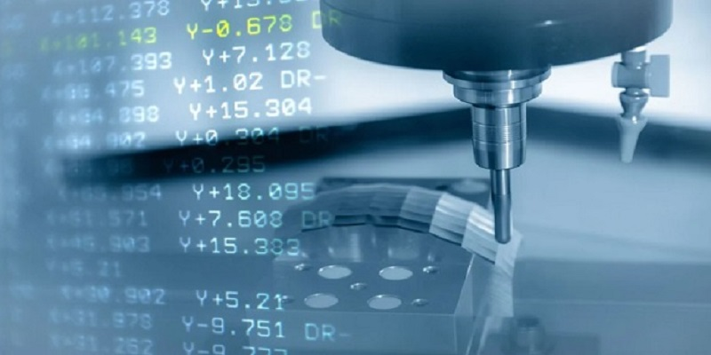
In CNC programming, a coordinate system is used to define the position of the cutting tool and the workpiece. The most common coordinate systems are Cartesian (X, Y, Z) and polar. The Cartesian coordinate system uses three axes (X, Y, and Z) to define a point in space, while the polar coordinate system uses an angle and a radius.

2.Tool Paths

Tool paths are the paths that the cutting tool follows to remove material from the workpiece. There are several types of tool paths, including linear, circular, and helical. The choice of tool path depends on the shape of the part and the machining operation being performed.

3.Feed Rates and Speeds

Feed rates and speeds determine how fast the cutting tool moves through the material. Feed rate is measured in inches per minute (IPM) or millimeters per minute (MMM), while speed is measured in revolutions per minute (RPM). The appropriate feed rates and speeds depend on factors such as the material being machined, the cutting tool, and the machining operation.

4.Tool Compensation

Tool compensation is used to account for the size and shape of the cutting tool. There are two types of tool compensation: radius compensation and length compensation. Radius compensation is used to adjust the tool path to account for the radius of the cutting tool, while length compensation is used to adjust the tool length to ensure accurate machining.

III. G-Codes

G-codes are a set of standardized programming instructions that are used to control the movement and operations of CNC machines. They are also known as preparatory functions, as they prepare the machine for a specific operation. Some of the most commonly used G-codes include:

1.G00 – Rapid Traverse This code is used to move the cutting tool quickly from one point to another without cutting. It is typically used for positioning the tool before a machining operation. 2. G01 – Linear Interpolation This code is used for linear movement at a specified feed rate. It is the most commonly used G-code for machining operations such as milling and turning.

2.G02/G03 – Circular Interpolation These codes are used for circular movement at a specified feed rate. G02 is used for clockwise circular interpolation, while G03 is used for counterclockwise circular interpolation.

3.G20/G21 – Inch/Metric Units These codes are used to select the unit of measurement for the CNC program. G20 selects inches, while G21 selects millimeters.

4.G40/G41/G42 – Tool Compensation These codes are used to enable or disable tool compensation and select the type of compensation (radius or length).

IV. M-Codes

M-codes are another set of programming instructions that are used to control auxiliary functions of CNC machines. They are also known as miscellaneous functions, as they perform tasks other than movement and machining operations. Some of the most commonly used M-codes include:

1. M00 – Program Stop This code stops the program execution and requires the operator to manually restart the program. It is typically used for inspection or tool change.

2. M03/M04/M05 – Spindle Control These codes are used to start, reverse, and stop the spindle motor. M03 starts the spindle in the forward direction, M04 starts the spindle in the reverse direction, and M05 stops the spindle.

3. M06 – Tool Change This code is used to perform a tool change. It stops the spindle, moves the tool to a tool change position, and loads a new tool.

4. M08/M09 – Coolant Control These codes are used to turn on and off the coolant system. M08 turns on the coolant, while M09 turns it off.

V. Conclusion

CNC programming is a complex and essential process in modern manufacturing. At TOP Prototype, we recognize the significance of this process and have dedicated teams working on advanced CNC programming solutions.

Understanding the basic concepts of CNC programming and the commonly used programming languages such as G-codes and M-codes is crucial for anyone involved in the field.

TOP Prototype’s experts are well-versed in these languages and use their knowledge to create highly precise and efficient programs. By mastering these concepts and languages, machinists at TOP Prototype can create programs that produce high-quality parts.

As technology continues to advance, CNC programming will become even more sophisticated. TOP Prototype is committed to staying at the forefront of these advancements, enabling the production of even more complex and advanced parts.

Let's Start A New Project Today

Latest Blog Posts

Check out the latest industry trends and take inspiration from our updated blogs, giving you a fresh insight to help boost your business.

Tapped Holes vs Threaded Holes – Differences and Comparison

Tapped Holes vs Threaded Holes – Differences and Comparison In mechanical manufacturing, assembly, and precision engineering, internal threaded holes serve as the “connective tissue” of components, enabling secure fastening, precise positioning, and stable load transmission. Tapped holes and threaded holes, two widely applied types of internal threaded structures, are often conflated due to their overlapping functional goals. Yet their divergence in processing principles, structural integrity, and practical performance is substantial—differences that directly affect product reliability, production costs, and service life. This article systematically distinguishes the two, enriches the discussion with industrial practices and material science facts, simplifies complex terminology, and reconstructs the logical framework to clarify their characteristics, advantages, and application boundaries for engineering practitioners. 1. Definitions and Core Structural Traits 1.1 Tapped Holes: Direct Thread Formation in Base Material A tapped hole is an internal threaded hole formed by the tapping process, where a specialized cutting tool (tap) cuts or forms threads on the inner wall of a pre-drilled pilot hole. Unlike indirect threading methods, tapped holes integrate threads directly into the workpiece’s base material—no auxiliary inserts or reinforcements are involved. Taps operate on a subtractive principle: they remove excess material from the pilot hole’s inner surface to form standardized thread profiles, such as metric (M series), unified coarse (UNC), or unified fine (UNF) threads, with precision grades ranging from 2B (general purpose) to 3B (high precision) for imperial threads. This integration with the base material means tapped holes’ performance is inherently tied to the workpiece’s material properties. For instance, in medium-carbon steel (e.g., 45# steel) or 6061 aluminum alloy—materials with moderate ductility and strength—tapped holes deliver reliable thread retention. They are widely adopted in scenarios where the workpiece itself can bear fastening loads, avoiding the need for additional components. 1.2 Threaded Holes: A Broad Category with Indirect Threading Dominance The term “threaded hole” is a generic concept encompassing all holes with internal threads, including tapped holes. In industrial practice, however, it primarily refers to holes where threads are formed indirectly—most commonly via threaded inserts. These inserts, made of high-strength materials like 304 stainless steel or titanium alloy, are installed into pre-drilled holes to provide the internal thread interface, decoupling thread performance from the workpiece’s base material. Beyond insert-based threading, threaded holes also include structures formed by thread rolling, casting, or injection molding. Thread rolling, for example, is used for high-volume production of ductile materials like copper or low-carbon steel, forming threads through plastic deformation rather than cutting. Cast or molded threaded holes are integral to composite parts (e.g., glass-fiber reinforced plastic) or plastic components, where threads are pre-designed in the mold to eliminate post-processing. 2. Core Differences in Processing Principles and Operations The fundamental gap between tapped holes and threaded holes lies in their thread formation mechanisms—each dictating processing efficiency, precision limits, and material applicability. Simplifying these mechanisms reveals why each is preferred in specific scenarios. 2.1 Tapped Holes: Two-Step Subtractive Processing Tapping follows a rigid two-step workflow: first, drilling a pilot hole with a diameter strictly matched to the target thread (e.g., a 6.8mm pilot hole for an M8×1.25 tap); second, cutting threads using a hand tap (for small batches or manual operations) or machine tap (for automated production on CNC lathes, milling machines, or dedicated tapping centers). Critical process parameters directly impact thread quality: tap speed (typically 10-30 m/min for steel, 20-50 m/min for aluminum), feed rate (matched to thread pitch to avoid thread distortion), and lubrication (cutting oil for ferrous metals, cutting fluid for non-ferrous metals to reduce friction and prevent burring). Brittle materials like gray cast iron (HT200) or zirconia ceramic require specialized spiral-flute taps to evacuate chips and avoid cracking, while ductile materials like copper demand straight-flute taps for smooth chip removal. 2.2 Threaded Holes: Indirect Formation with Diversified Methods Insert-based threaded holes, the most common type, follow a three-step process: drilling a hole matching the insert’s outer diameter (e.g., a 10.2mm hole for an M8 helical insert), installing the insert via pressing, self-tapping, or adhesive bonding, and verifying thread accuracy. Helical wire inserts (HeliCoils), for example, are coiled stainless steel wires with a diamond cross-section—when installed, they expand to lock into the pre-drilled hole, distributing fastening loads over a larger surface area to prevent thread stripping. Other threading methods for threaded holes have clear niche applications: thread rolling achieves higher thread strength (up to 30% higher than cut threads due to work hardening) and is used for high-volume parts like automotive bolts; casting/molding eliminates post-processing but is limited to parts with simple thread geometries, as complex threads may cause mold release issues. 3. Performance Comparison and Practical Application Scenarios Evaluating strength, precision, cost, and maintainability reveals the practical trade-offs between tapped holes and threaded holes. Grounded in industrial data and real-world cases, this comparison helps engineers make evidence-based selections. …

Analysis of Causes and Solutions of Surface Roughness Issues in CNC Machining

Analysis of Causes and Solutions of Surface Roughness Issues in CNC Machining In CNC machining, surface roughness is critical—it directly …

TOP Prototype CNC Customization Precision Machining Tailored Solutions for Global Industrial Innovation   The Art and Science of TOP Prototype CNC Customization   CNC customization blends engineering precision with creative …

Scroll to Top

Contact Us

Upload Your Files to Get Instant Quote and DFM Feedback
(Please attach 2D CAD drawings and 3D CAD models in any format including STEP,STP, IGES, DWG, PDF, STL, PDF, JPG , ZIP, RAR, etc