• Home
  • Resources
  • Blogs
  • An Exhaustive Exploration of Working Principles, Machine Components, and Production Benefits

An Exhaustive Exploration of Working Principles, Machine Components, and Production Benefits

An Exhaustive Exploration of Working Principles, Machine Components, and Production Benefits

An Exhaustive Exploration of Working Principles, Machine Components, and Production Benefits

CNC Machines
CNC Machines

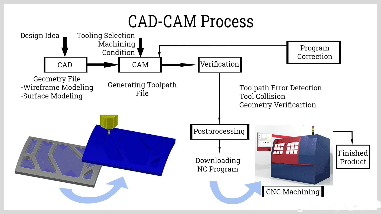
CAD – CAM refers to the software used for designing and machining parts and components with a CNC machine. TOP Prototype utilizes this advanced technology. CAD (Computer – Aided Design) software is used to design, draw, and shape parts using geometric shapes and constructs at TOP Prototype.

CAM (Computer – Aided Manufacturing) software, in turn, takes the information from CAD and converts it into machine language, known as G – Code. Before converting the CAD – designed model into machine language, CAM software at TOP Prototype determines the cutting paths for the tools to remove excess material from the workpiece. CAD and CAM work together at TOP Prototype to provide the CNC machine with precise and accurate instructions for executing the required cutting operations.

Process of CAD-CAM
Process of CAD-CAM

The computer moves the tool or workpiece and controls the feed rate, cut depth, speed, and coolant flow. As the machine operates, it precisely removes material layer by layer to shape the workpiece. CNC machines can work on various materials, including metals, plastics, woods, and composites.
There are many different types of CNC machines, with each performing different functions. Standard CNC machining processes include these machining techniques:

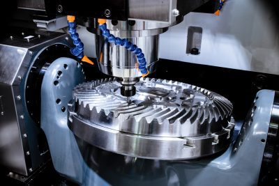
1.Milling— A spinning cutting tool makes contact with a fixed workpiece

2.Turning— Spinning the workpiece while a cutting tool shapes it; typically done with lathes

3.Drilling— A rotating cutting tool cuts holes into a workpiece

4.Boring— Creating a precise internal cavity in a workpiece by material removal

5.Broaching— Sequential material removal with shallow cutting strokes

6.Sawing— Slicing a workpiece using the back-and-forth motion of a saw blade

Although the types of CNC machines vary quite a bit, no matter what the task, a CNC machine clearly excels in two ways: repeatability (the ability to make tens of thousands of identical parts) and precision (hitting position tolerances of +/- .001” or tighter).

We look forward to serving you

Working Principles of TOP Prototype CNC


Programming: The first step in the CNC process is creating a program. This program contains a series of instructions that tell the machine what operations to perform. The instructions are typically written in a specific programming language, such as G-code or M-code.

G-code: This code is used to control the movement of the machine tool. It includes commands for linear and circular interpolation, as well as for setting the feed rate and spindle speed.

M-code: M-code is used for miscellaneous functions, such as turning the coolant on and off, changing tools, and starting and stopping the spindle.

Machining Center Tool Construction

Machine Control Unit (MCU): Once the program has been created, it is loaded into the machine control unit. The MCU is the brain of the CNC machine and is responsible for interpreting the program instructions and sending signals to the machine’s motors and actuators.

Motion Control: The machine’s motors and actuators receive signals from the MCU and move the cutting tool or workpiece according to the programmed instructions. The motion control system ensures that the movements are precise and accurate, enabling high-quality machining.

Feedback System: A feedback system is used to monitor the position and movement of the machine’s axes. This system typically consists of encoders or other sensors that provide real-time feedback to the MCU. The MCU uses this feedback to make adjustments to the machine’s movements to ensure accuracy.


Components of a CNC Machine


Machine Tool: This is the physical part of the CNC machine that performs the cutting or shaping operations. It can be a lathe, mill, router, or other type of machine tool.


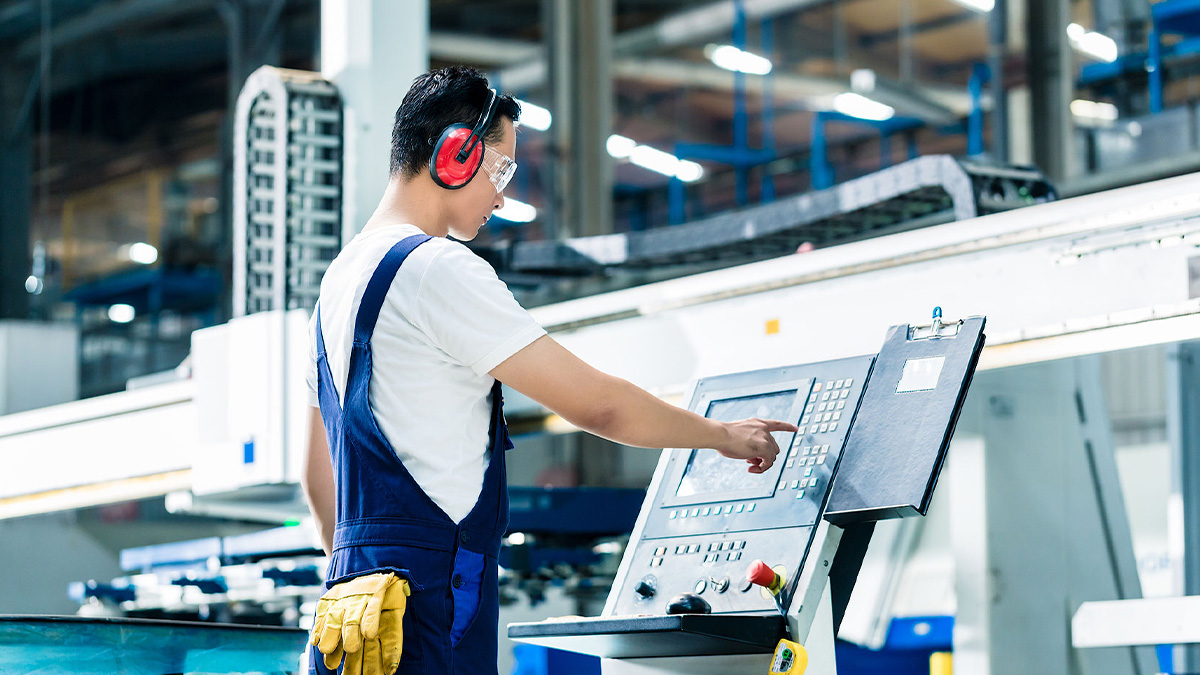
Control Panel: The control panel is used to input commands and monitor the machine’s operation. It typically includes buttons, switches, and a display screen.


Drive System: The drive system consists of motors and actuators that move the machine’s axes. It can be a servo drive system or a stepper drive system.


Tool Changer: In some CNC machines, a tool changer is used to automatically change tools during the machining process. This allows for more complex operations to be performed without the need for manual tool changes.


Benefits of TOP Prototype CNC Machining


High Precision: CNC machines are capable of extremely high precision, with tolerances as small as a few microns. This makes them ideal for manufacturing complex parts with tight tolerances.

Repeatability: Once a program has been created, the CNC machine can reproduce the same part over and over again with consistent quality. This is important for mass production.

Efficiency: CNC machines can operate continuously, 24 hours a day, 7 days a week. They can also perform multiple operations simultaneously, reducing production time and increasing efficiency.

Flexibility: CNC machines can be easily reprogrammed to produce different parts. This makes them suitable for small-batch production as well as mass production.
CNC Machine Setup

Worker operating CNC machine
worker is operating

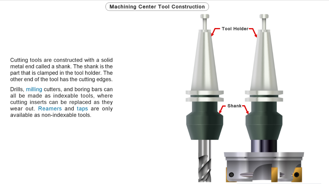
Before downloading the CAD-CAM program into the machine, it must be equipped with the appropriate cutting tools. Tool changing can be done in two ways: the first method involves selecting tools from a tool cart and manually placing them into the machine.

The second method involves an Automatic Tool Changer (ATC), which stores tools on a drum or chain. When programmed with the necessary tools, the ATC automatically removes the old tool and inserts the new one. The ATC is designed to save time and enhance efficiency.

A crucial aspect of CNC machine setup is establishing the gauge point, which measures the distance from the tool tip to a reference point. Properly setting this gauge point ensures that the tool cuts to the correct depth.

One of the final steps in CNC machine setup is testing the coolant or lubricant. Coolant can be delivered through air, mist, flood, or high pressure. It’s crucial to check the pressure at which the coolant is delivered, as incorrect pressure can damage the tool, while an incorrect amount can harm the machine and equipment.

A common mistake during CNC machine setup is neglecting to check the coolant, which might have an unpleasant odor, be insufficient in quantity, have a low concentration, or be improperly filtered.

Conclusion


CNC machining is a highly advanced and efficient manufacturing process that has become an essential part of modern industry. TOP Prototype, with its professional expertise, focuses on this field. By understanding the working principles and components of CNC machines, operators at TOP Prototype can optimize their performance and produce high-quality parts with ease.

Other Information of CNC Machining you may want: 5-Axis-CNC machining     Swiss Lathe Processing

Let's Start A New Project Today

Latest Blog Posts

Check out the latest industry trends and take inspiration from our updated blogs, giving you a fresh insight to help boost your business.

Tapped Holes vs Threaded Holes – Differences and Comparison

Tapped Holes vs Threaded Holes – Differences and Comparison In mechanical manufacturing, assembly, and precision engineering, internal threaded holes serve as the “connective tissue” of components, enabling secure fastening, precise positioning, and stable load transmission. Tapped holes and threaded holes, two widely applied types of internal threaded structures, are often conflated due to their overlapping functional goals. Yet their divergence in processing principles, structural integrity, and practical performance is substantial—differences that directly affect product reliability, production costs, and service life. This article systematically distinguishes the two, enriches the discussion with industrial practices and material science facts, simplifies complex terminology, and reconstructs the logical framework to clarify their characteristics, advantages, and application boundaries for engineering practitioners. 1. Definitions and Core Structural Traits 1.1 Tapped Holes: Direct Thread Formation in Base Material A tapped hole is an internal threaded hole formed by the tapping process, where a specialized cutting tool (tap) cuts or forms threads on the inner wall of a pre-drilled pilot hole. Unlike indirect threading methods, tapped holes integrate threads directly into the workpiece’s base material—no auxiliary inserts or reinforcements are involved. Taps operate on a subtractive principle: they remove excess material from the pilot hole’s inner surface to form standardized thread profiles, such as metric (M series), unified coarse (UNC), or unified fine (UNF) threads, with precision grades ranging from 2B (general purpose) to 3B (high precision) for imperial threads. This integration with the base material means tapped holes’ performance is inherently tied to the workpiece’s material properties. For instance, in medium-carbon steel (e.g., 45# steel) or 6061 aluminum alloy—materials with moderate ductility and strength—tapped holes deliver reliable thread retention. They are widely adopted in scenarios where the workpiece itself can bear fastening loads, avoiding the need for additional components. 1.2 Threaded Holes: A Broad Category with Indirect Threading Dominance The term “threaded hole” is a generic concept encompassing all holes with internal threads, including tapped holes. In industrial practice, however, it primarily refers to holes where threads are formed indirectly—most commonly via threaded inserts. These inserts, made of high-strength materials like 304 stainless steel or titanium alloy, are installed into pre-drilled holes to provide the internal thread interface, decoupling thread performance from the workpiece’s base material. Beyond insert-based threading, threaded holes also include structures formed by thread rolling, casting, or injection molding. Thread rolling, for example, is used for high-volume production of ductile materials like copper or low-carbon steel, forming threads through plastic deformation rather than cutting. Cast or molded threaded holes are integral to composite parts (e.g., glass-fiber reinforced plastic) or plastic components, where threads are pre-designed in the mold to eliminate post-processing. 2. Core Differences in Processing Principles and Operations The fundamental gap between tapped holes and threaded holes lies in their thread formation mechanisms—each dictating processing efficiency, precision limits, and material applicability. Simplifying these mechanisms reveals why each is preferred in specific scenarios. 2.1 Tapped Holes: Two-Step Subtractive Processing Tapping follows a rigid two-step workflow: first, drilling a pilot hole with a diameter strictly matched to the target thread (e.g., a 6.8mm pilot hole for an M8×1.25 tap); second, cutting threads using a hand tap (for small batches or manual operations) or machine tap (for automated production on CNC lathes, milling machines, or dedicated tapping centers). Critical process parameters directly impact thread quality: tap speed (typically 10-30 m/min for steel, 20-50 m/min for aluminum), feed rate (matched to thread pitch to avoid thread distortion), and lubrication (cutting oil for ferrous metals, cutting fluid for non-ferrous metals to reduce friction and prevent burring). Brittle materials like gray cast iron (HT200) or zirconia ceramic require specialized spiral-flute taps to evacuate chips and avoid cracking, while ductile materials like copper demand straight-flute taps for smooth chip removal. 2.2 Threaded Holes: Indirect Formation with Diversified Methods Insert-based threaded holes, the most common type, follow a three-step process: drilling a hole matching the insert’s outer diameter (e.g., a 10.2mm hole for an M8 helical insert), installing the insert via pressing, self-tapping, or adhesive bonding, and verifying thread accuracy. Helical wire inserts (HeliCoils), for example, are coiled stainless steel wires with a diamond cross-section—when installed, they expand to lock into the pre-drilled hole, distributing fastening loads over a larger surface area to prevent thread stripping. Other threading methods for threaded holes have clear niche applications: thread rolling achieves higher thread strength (up to 30% higher than cut threads due to work hardening) and is used for high-volume parts like automotive bolts; casting/molding eliminates post-processing but is limited to parts with simple thread geometries, as complex threads may cause mold release issues. 3. Performance Comparison and Practical Application Scenarios Evaluating strength, precision, cost, and maintainability reveals the practical trade-offs between tapped holes and threaded holes. Grounded in industrial data and real-world cases, this comparison helps engineers make evidence-based selections. …

Analysis of Causes and Solutions of Surface Roughness Issues in CNC Machining

Analysis of Causes and Solutions of Surface Roughness Issues in CNC Machining In CNC machining, surface roughness is critical—it directly …

TOP Prototype CNC Customization Precision Machining Tailored Solutions for Global Industrial Innovation   The Art and Science of TOP Prototype CNC Customization   CNC customization blends engineering precision with creative …

Scroll to Top

Contact Us

Upload Your Files to Get Instant Quote and DFM Feedback
(Please attach 2D CAD drawings and 3D CAD models in any format including STEP,STP, IGES, DWG, PDF, STL, PDF, JPG , ZIP, RAR, etc