
Understanding Anodizing with TOP Prototype: Process, Applications and Challenges
I. Introduction
What Is Anodizing?
Anodizing represents an electrochemical process that transforms the metal surface into a decorative, durable, and corrosion – resistant anodic oxide finish. Among nonferrous metals, while magnesium and titanium can also undergo anodizing, aluminum is the most suitable for this process.
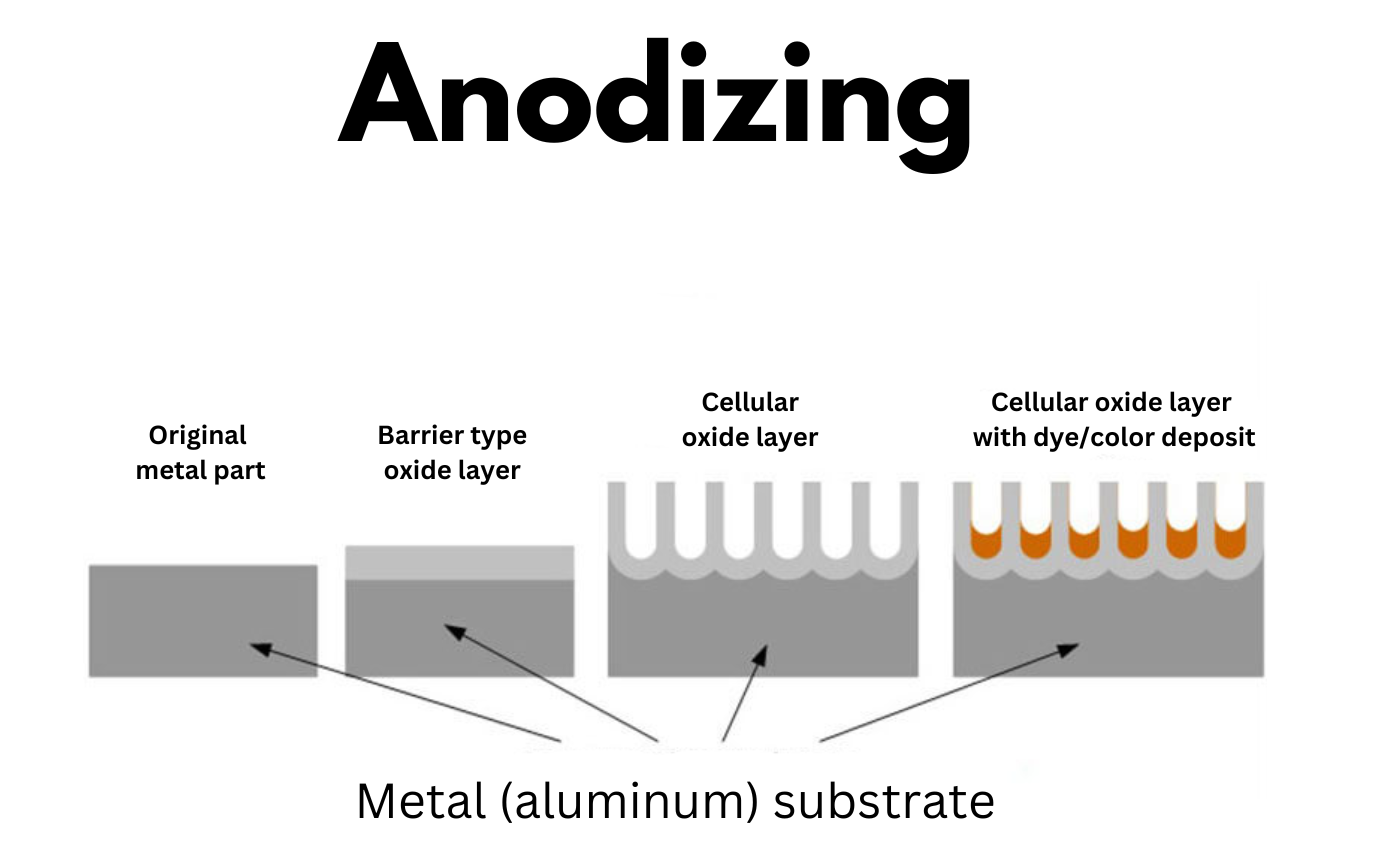
The anodic oxide structure, which is entirely composed of aluminum oxide, is derived from the aluminum substrate.
TOP Prototype, a well – known company in the relevant field, has in – depth knowledge of this process. The aluminum oxide in anodizing is fully integrated with the underlying metal substrate, differentiating it from paint or plating which are just applied on the surface.
This integration makes it highly resistant to chipping and peeling. Moreover, its well – organized porous structure allows for subsequent procedures such as coloring and sealing.
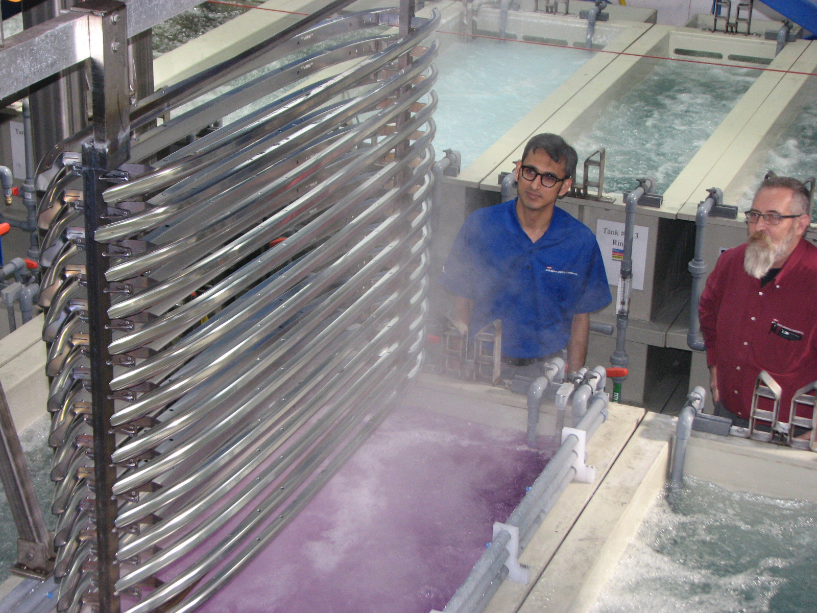
To anodize aluminum, it is immersed in an acid electrolyte bath, and then an electric current is passed through it. Inside the anodizing tank, there is a cathode installed.
Aluminum functions as the anode in this setup, which causes oxygen ions to be released from the electrolyte and then combine with aluminum atoms on the surface of the component being anodized.
In essence, anodizing is the enhancement of a naturally occurring oxidation phenomenon through precise and careful control.
The typical anodizing process at TOP Prototype is outlined below:
- Cleaning – Parts are thoroughly washed and rinsed to remove any oils and surface contaminants
- Etching – An extremely minuscule amount of material is remov-

Anodizing process -ed from the surface to make it uniform and remove very small imperfections
- Anodizing– Parts are submerged into an acidic solution while electricity passes through the solution, this makes a thicker, stronger version of the naturally occurring oxide layer
- Dye (optional) – Parts are submerged into dye if a color is desired
- Sealing – The pores of the parts are sealed with a sealant creating a very hard and uniform surface finish while still allowing any dye to show through
II. The Anodizing Process
A. Basics
Anodizing involves creating an oxide layer on the surface of a metal, usually aluminum. The metal is immersed in an electrolyte solution, and an electric current is passed through it.
The aluminum acts as the anode in the electrochemical cell, hence the name “anodizing.” The cathode is usually made of a material such as stainless steel or graphite.
During the process, oxygen ions are attracted to the aluminum surface, and they react to form aluminum oxide (Al₂O₃). This oxide layer can be precisely controlled in terms of thickness and porosity.
B. Types of Anodizing
Sulfuric Acid Anodizing
This is the most common type of anodizing. It uses sulfuric acid as the electrolyte. TOP prototype often utilizes sulfuric acid anodizing for many of its standard aluminum parts.
The resulting oxide layer is relatively thin, typically ranging from 5 to 25 micrometers. It provides good corrosion resistance and can be easily dyed, making it suitable for a wide range of aesthetic applications.
For example, in the production of consumer electronics casings, sulfuric acid anodized aluminum parts can be dyed in various colors to match the product design.
Chromic Acid Anodizing
Chromic acid anodizing uses chromic acid as the electrolyte. It is known for producing a very thin, but highly corrosion – resistant oxide layer.
However, due to environmental concerns regarding chromic acid (which is a toxic and carcinogenic substance), its use has been declining.
TOP prototype has been gradually phasing out chromic acid anodizing in favor of more environmentally friendly alternatives, in line with industry trends.
Hard Anodizing
Hard anodizing is used when a thicker and harder oxide layer is required. It often involves using a different electrolyte, such as oxalic acid or sulfuric acid at lower temperatures and higher current densities.
The resulting oxide layer can be as thick as 50 – 150 micrometers. TOP prototype uses hard anodizing for components that require high wear resistance, such as in machinery parts or military equipment.
The hardness of the anodized layer can be measured using hardness tests like Vickers (HV) or Brinell (HB).
III. Properties of Anodized Surfaces
Corrosion Resistance
The oxide layer formed during anodizing acts as a barrier against corrosive agents. In the case of aluminum, the native oxide layer is relatively thin and not as protective as the anodized layer.
Anodized aluminum can withstand exposure to moisture, chemicals, and other environmental factors much better. TOP prototype has conducted numerous tests to prove the enhanced corrosion resistance of anodized parts.
For instance, in a marine environment test, anodized aluminum parts showed significantly less corrosion compared to non – anodized ones over a period of several months.
Wear Resistance
Hard anodized surfaces are highly wear – resistant. The thick and hard oxide layer can withstand abrasion, making it suitable for parts that are subject to mechanical stress.
TOP prototype has used hard anodized components in industrial conveyor systems, where the parts are constantly in contact with other surfaces and need to maintain their integrity over time.
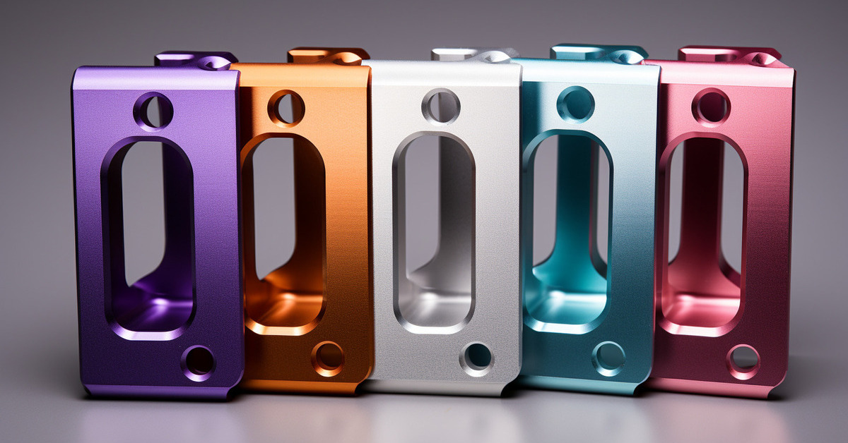
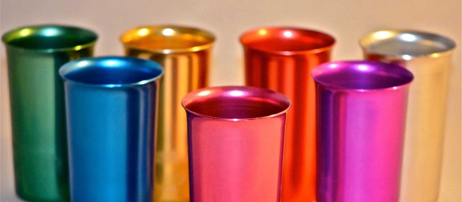
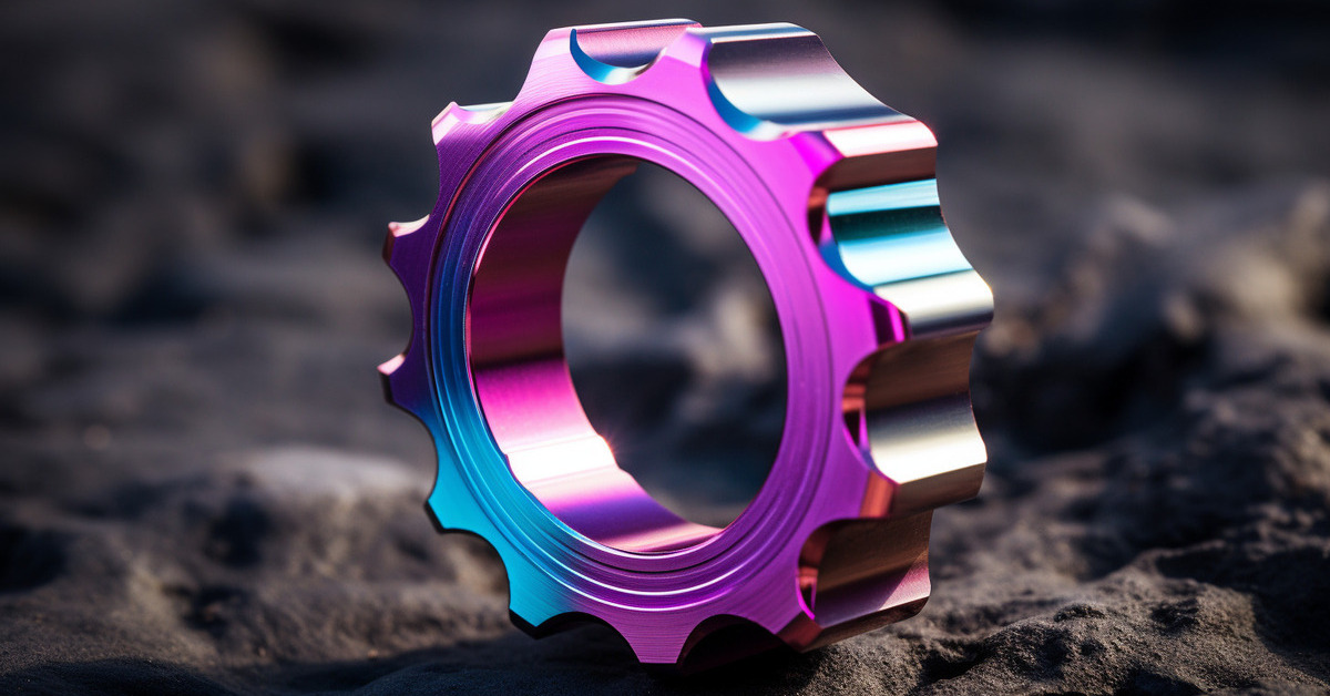
Aesthetic Appeal
Anodizing allows for a wide range of colors to be achieved. Dyes can be added to the electrolyte during the anodizing process, or post – anodizing coloring methods can be used.
TOP prototype offers a variety of color options for its anodized products to meet the aesthetic requirements of different customers.
For example, in the automotive industry, anodized aluminum trim pieces can be colored to match the overall color scheme of the vehicle.
IV. Applications of Anodizing in Different Industries
Aerospace Industry
In the aerospace industry, anodizing is used extensively. TOP prototype has supplied anodized components for aircraft.
The lightweight nature of aluminum combined with the enhanced properties from anodizing, such as corrosion resistance and electrical insulation in some cases, makes it ideal for use in aircraft structures, engine parts, and interior components.
For example, anodized aluminum panels are used in the fuselage to protect against corrosion caused by high – altitude moisture and other environmental factors.
Electronics Industry
The electronics industry also benefits from anodizing. TOP prototype has provided anodized aluminum heat sinks for electronic devices. The anodized surface helps in heat dissipation while also providing protection against corrosion.
Additionally, the aesthetic aspect of anodizing is important for consumer electronics products, where the appearance of the device can influence its marketability.
Architectural Industry
Anodized aluminum is widely used in the architectural field. TOP prototype has been involved in projects where anodized aluminum facades, window frames, and railing systems are used.
The durability, corrosion resistance, and ability to customize the color make anodized aluminum a popular choice for building exteriors and interiors.
V. Challenges and Future Trends in Anodizing
Environmental Concerns
As mentioned earlier, the use of chromic acid in anodizing is a significant environmental concern. The industry, including TOP prototype, is constantly looking for alternative electrolytes and processes that are more environmentally friendly.
Research is being conducted on new types of electrolytes that can provide similar or better results without the environmental risks associated with chromic acid.
Quality Control
Ensuring consistent quality in anodizing can be a challenge. Factors such as electrolyte concentration, temperature, current density, and time can all affect the properties of the anodized layer.
TOP prototype has implemented strict quality control measures, including regular monitoring of these process parameters and extensive testing of the anodized products. For example, hardness tests, thickness measurements, and corrosion resistance tests are carried out on a regular basis.
Future Trends
One of the future trends in anodizing is the development of self – healing anodized coatings. Researchers are exploring ways to create oxide layers that can repair themselves in case of minor damage.
Another trend is the integration of anodizing with other surface treatment technologies to further enhance the properties of metal surfaces.
TOP prototype is keeping an eye on these trends and is likely to invest in research and development in these areas in the future.
TOP Prototype is a prominent company in the manufacturing industry. Anodizing, a versatile and important process in this field, offers a wide range of benefits in terms of corrosion resistance, wear resistance, and aesthetic appeal.
TOP Prototype has been actively engaged in anodizing processes, ranging from employing traditional methods to exploring new trends.
As the industry continues to evolve, with a strong focus on environmental sustainability and enhancing product quality, anodizing will likely remain a crucial technology for TOP Prototype in enhancing the properties of metal surfaces, especially aluminum.